


3-32
Cisco 10008 Router Hardware Installation Guide
OL-0659-13
Chapter 3 Installing the Cisco 10008 Router
Connecting Network Management and Signal System Cables
Step 6 Go to the “Connecting Network Management and Signal System Cables” section on page 3-32 to
continue the installation.
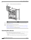
Connecting Network Management and Signal System Cables
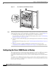
The Cisco 10008 router has connections to both the internal Ethernet management network and the
external data network.
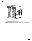
• The internal Ethernet management network connections are made through an Ethernet port on the
front panel of the PRE module.
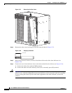
• The external data network connections are made through DS3 connectors on the router’s backplane,
and through the front panel ports on several types of line cards.
Keep the following guidelines in mind when connecting external cables to the Cisco 10008 router:
• To reduce the chance of interference, avoid crossing high-power lines with any interface cables.
• Verify all cabling limitations (particularly distance) before powering on the system.
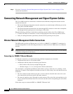
Ethernet Network Management Cable Connections
The PRE module provides an Ethernet port to a LAN for a 10BASE-T or 100BASE-T connection for
network management. Use the following procedures to connect the Cisco 10008 router to an Ethernet
network.
Note Each PRE must have an Ethernet port connection (typically to the same Ethernet hub) if you are running
a redundant configuration in the chassis.
Connecting to a 10BASE-T Ethernet Network
To make this connection, you need the following additional equipment (not included):
• An Ethernet hub (such as a Cisco Micro Hub)
• An Ethernet cable that meets the following specifications:
–
RJ-45 (male) to RJ-45 (male) straight-through cable
–
100-ohm category 3, 4, or 5, no longer than 328 feet (100 meters)
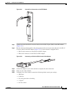
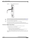
You can identify a straight-through Ethernet cable either by using a cable tester or by making a visual
inspection. To make a visual inspection, hold the two ends of a cable side by side, with the tab for each
at the back.
• The wire connected to the left-most pin (pin 1) on one connector should be the same color as the
wire connected to the left-most pin on the other connector.
• The same rule applies to pins 2 through 8 on each connector. The color of the wire attached to a pin
on one connector should match the color of the wire attached to the corresponding pin on the other
connector.
Follow these steps to connect the PRE to a 10BASE-T Ethernet LAN: