


2-10
Cisco 10008 Router Hardware Installation Guide
OL-0659-13
Chapter 2 Preparing for Installation
Site Planning
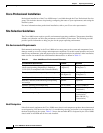
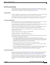
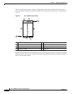
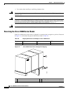
The Cisco 10008 chassis draws cooling air in through the intake vent in the front and moves the air
across the internal components and out the exhaust vents on the top rear of the chassis, as illustrated in
Figure 2-1.
Figure 2-1 Cisco 10008 Chassis Airflow
Keep the front and top of the Cisco10008 chassis clear to ensure proper airflow and prevent overheating
inside the chassis. Allow at least 3 inches of clearance between the top of the chassis and the equipment
above to ensure proper airflow.
1 Blower module (fans) 5 Bottom
2 Top 6 Air filter assembly
3 Front 7 Rear
4 Ambient air intake 8 Exhaust air
132843
1
6
3
4
2
7
5
8