


1-6
Cisco 10008 Router Hardware Installation Guide
OL-0659-13
Chapter 1 Cisco 10008 Router Overview
Cisco 10008 Router Hardware Description
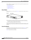
The Cisco 10008 chassis is designed for mounting in 19-inch or (optional) 23-inch equipment racks, and
contains the following components:
• Blower Module, page 1-6
• Power Entry Modules, page 1-6
• Connector Ports, page 1-9
• PCMCIA Card Slots, page 1-10
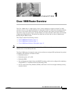
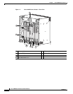
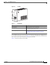
Blower Module
The Cisco 10008 router uses a blower module (Figure 1-3) containing four fans to supply cooling air to
the chassis.
Figure 1-3 Blower Module
The blower module is located at the top of the chassis and connects to a connector on the chassis.
1. Four internal fans draw cooling air into the front of the chassis and directs it across the internal
components to maintain an acceptable operating temperature.
2. The air is exhausted through openings in the rear of the chassis.
Although the blower module supports hot-swapping and can be replaced without interruption to system
operation, do not power down the system without the blower unit for more than a few minutes to prevent
overheating.
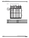
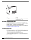
Power Entry Modules
The DC PEM provides filtering and supplies DC power to the chassis electronics (Figure 1-4). DC PEMs
receive input power (–48 VDC from building centralized power source) through terminal block
connections located on the rear of the chassis.
Table 1-1 describes the LEDs on the DC PEM.
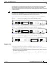
30002
FANS
OK
FAN
FAILURE
MULTI-
FAN
FAILURE
W
hen hot sw
ap
ping
this fa
n tra
y,
rem
o
va
l and
re
pla
cem
e
nt m
u
st
b
e do
ne in
und
er tw
o
m
inu
te
s or
system
shutdow
n w
ill occur.
C
A
U
T
IO
N