


5-12
Cisco 10008 Router Hardware Installation Guide
OL-0659-13
Chapter 5 Maintaining the Cisco 10008 Router
Removing and Replacing Field-Replaceable Units
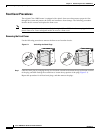
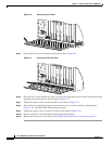
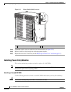
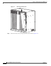
Figure 5-13 Blower Module Cable Connector
Step 5
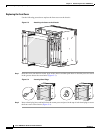
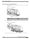
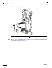
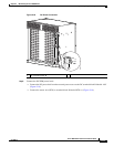
Tighten the captive screws on each side of the blower module (see Figure 5-12).
Step 6 Rerun all interface cables through the cable management brackets.
Step 7 Replace the front cover if necessary (see the “Replacing the Front Cover” section on page 5-6).
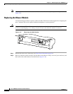
Installing Power Entry Modules
This section contains the procedures to install or replace AC or DC PEMs.
Note If you are adding a second PEM for redundancy, or if you have redundant PEMs, it is not necessary to
shut down the system before replacing a PEM.
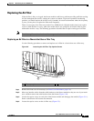
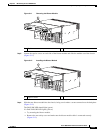
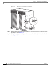
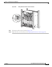
Installing a Second DC PEM
Use the following procedure to install a second DC PEM in the bottom power bay for redundancy.
Caution Do not power off the primary DC PEM or all data traffic will halt.
1 Blower module connector
132835
1