


3-30
Cisco 10008 Router Hardware Installation Guide
OL-0659-13
Chapter 3 Installing the Cisco 10008 Router
Connecting a Video Terminal to the PRE Console Port
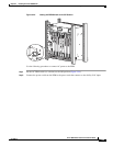
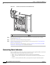
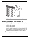
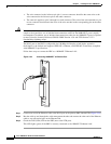
Figure 3-30 Alarm Indicator Wires Exiting Safety Cover
Step 8 Go to the “Connecting a Video Terminal to the PRE Console Port” section on page 3-30 to continue the
installation.
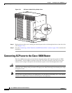
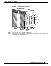
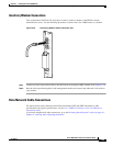
Connecting a Video Terminal to the PRE Console Port
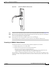
The Cisco 10008 router PRE module has an asynchronous serial (EIA/TIA-232) RJ-45 console port
labeled CON on its front panel. You can connect this port to most types of video terminals through use
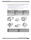
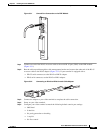
of the console cable kit that is included with your Cisco 10008 router. The console cable kit contains:
• One RJ-45 to RJ-45 crossover cable
• One RJ-45 to DB-25 (female) adapter
• One RJ-45 to DB-9 (female) adapter
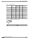
A crossover cable reverses pin connections from one end to the other. In other words, it connects pin 1
(at one end) to pin 8 (at the other end), pin 2 to pin 7, pin 3 to pin 6, and so on. You can identify a
crossover cable by comparing the two modular ends of the cable. Hold the cable ends in your hand,
side-by-side, with the tabs at the back. Ensure that the wire connected to the outside (left) pin of the left
plug (pin 1) is the same color as the wire connected to the outside (right) pin of the right plug (pin 8).
Use the following procedure to connect a video terminal to the console port on a PRE module.
Note Each PRE must have a console port connection (typically to a terminal server) if you are running a
redundant configuration in the chassis.
32693