


3-28
Cisco 10008 Router Hardware Installation Guide
OL-0659-13
Chapter 3 Installing the Cisco 10008 Router
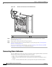
Connecting Alarm Indicators
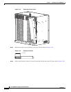
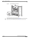
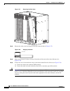
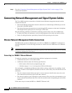
Figure 3-27 Removing the Rear Cover
Step 2 Remove the safety cover by lifting it up and out from the chassis (Figure 3-27).
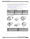
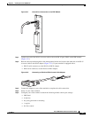
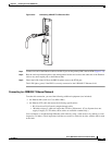
Figure 3-28 Stripping Insulation
Step 3
Strip not more than 0.4 inches (10 mm) of insulation off the ends of the alarm indicator wire
(Figure 3-28).
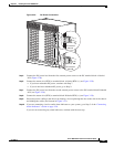
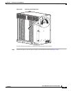
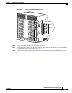
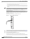
Step 4 Connect one set of alarm indicator wires to the alarm terminal block as follows (see Figure 3-29):
a. Connect one lead to the common (COM) terminal.
b. Connect the other lead to the normally closed (NC) or normally open (NO) terminal.
Caution Figure 3-29 shows the wiring configuration for normally open (NO) alarm relays. If you are wiring the
router in series with other equipment for the alarm indicators, use the normally closed (NC) terminals.
If you are wiring the router in parallel with other equipment for the alarm indicators, use the NO
terminals.
30023
14747
10 mm max