


5-35
Cisco 10008 Router Hardware Installation Guide
OL-0659-13
Chapter 5 Maintaining the Cisco 10008 Router
Connecting Alarm Indicators
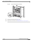
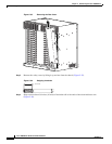
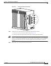
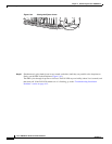
Figure 5-37 Alarm Terminal Block Connections
Step 5 Connect one set of alarm indicator wires to the alarm terminal block as follows:
a. Connect one lead to the common (COM) terminal (Figure 5-37).
b. Connect the other lead to the normally closed (NC) or normally open (NO) terminal.
Caution Figure 5-37 shows the wiring configuration for normally open (NO) alarm relays. If you are wiring the
router in series with other equipment for the alarm indicators, use the normally closed (NC) terminals.
If you are wiring the router in parallel with other equipment for the alarm indicators, use the NO
terminals.
Step 6 Repeat steps 1 and 2 for any remaining alarm indicators.
32694
MINOR
MAJOR
CRITICAL
ALARMS
50VA
SELV max
NC
COM
NO
NC
COM
NO
NC
COM
NO