


5-17
Cisco 10008 Router Hardware Installation Guide
OL-0659-13
Chapter 5 Maintaining the Cisco 10008 Router
Removing and Replacing Field-Replaceable Units
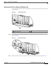
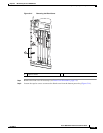
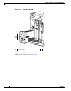
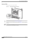
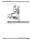
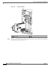
Figure 5-18 DC Power Connection
Step 6
Connect the DC PEM power leads:
• Connect the DC power lead from the external power source to the DC terminal block B labeled –48V
(Figure 5-18).
• Connect the return wire (RTN) to terminal block B labeled RTN (+) (Figure 5-18).
1 DC terminal block B
132830
RTN (+)
–48/–60
V
1