


3-11
Cisco 10008 Router Hardware Installation Guide
OL-0659-13
Chapter 3 Installing the Cisco 10008 Router
Non-Rack Installation
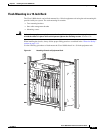
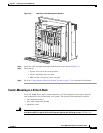
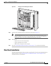
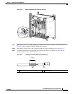
Figure 3-9 Attaching the Cable Management Bracket
Step 5
Attach the cable management bracket to the bottom of the chassis (Figure 3-9).
Note The cable management bracket consists of two pieces (the cable guide and channel), and is
shipped assembled. If you want to use the cable guide only, you can remove the channel by
loosening the captive screws before attaching the cable guide to the chassis.
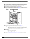
Step 6 Check that all
–
Ejector levers are in the closed position.
–
Chassis mounting screws are tight.
–
PRE and line card captive screws are tight.
Step 7 Go to the “Connecting the Chassis to Ground” section on page 3-13 to continue the installation.
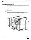
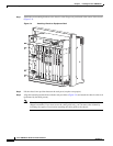
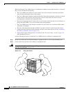
Non-Rack Installation
The chassis should already be in the area where you will install it. If you have not determined where to
install your chassis, see the “Receiving the Cisco 10000 Series Router” section on page 2-14 for
information about site considerations.
76223
1
3
2
4
0A
PROCESSOR ONLY
0B
5
6
7
8
PROCESSOR ONLY
P
O
W
E
R
F
A
U
L
T
M
IS
W
IR
E
P
O
W
E
R
F
A
U
LT
M
IS
W
IR
E
CISCO
10000
LIN
K
TX
RX
F
A
IL
GIGABIT ETHERNET
C
IS
C
O
100
0
0
CARRIER
ALARM
LOOP
FAIL
CH OC-12-DSO SM-IR
C
IS
C
O
1
0
0
0
0
C
AR
R
IE
R
A
LA
RM
L
O
OP
F
A
I
L
6XCT3–DS0
0
5
4
3
2
1
C
IS
C
O
1
0
0
0
0
C
A
R
R
IE
R
A
L
A
RM
L
O
O
P
F
A
I
L
6XCT3–DS0
0
5
4
3
2
1
F
A
IL
PERFORMANCE ROUTING ENGINE
C
O
N
S
O
L
E
S
T
A
T
U
S
A
C
O
C
R
IT
IC
A
L
M
IN
O
R
M
A
J
O
R
E
TH
E
R
N
E
T
L
I
NK
A
C
T
IV
IT
Y
A
U
X
S
L
O
T
0
S
L
O
T
1
F
A
IL
PERFORMANCE ROUTING ENGINE
C
O
N
S
O
L
E
S
T
A
T
U
S
A
C
O
C
R
IT
I
C
A
L
M
I
N
O
R
M
A
J
O
R
E
TH
E
R
N
ET
L
INK
AC
TI
V
IT
Y
A
UX
S
L
O
T
0
S
L
O
T
1
C
IS
C
O
1
0
0
0
0
C
AR
RIE
R
A
LAR
M
LO
O
P
F
A
I
L
6XCT3–DS0
0
5
4
3
2
1
C
IS
C
O
1
0
0
0
0
C
AR
R
IE
R
ALA
R
M
LO
O
P
F
A
I
L
6XCT3–DS0
0
5
4
3
2
1
C
IS
C
O
1
0
0
0
0
C
A
R
R
IE
R
A
LA
R
M
LO
O
P
F
A
I
L
6XCT3–DS0
0
5
4
3
2
1
C
IS
C
O
1
0
0
0
0
C
A
R
RI
ER
TX
R
X
F
A
I
L
OC–12/STM–4 POS SM–IR
C
I
S
C
O
1
0
0
0
0
C
IS
C
O
1
0
0
0
0
F
A
N
S
O
K
F
A
N
F
A
IL
U
R
E
M
U
L
T
I
-
F
A
N
F
A
IL
U
R
E
When hot swapping this fan tray,
removal and replacement must
be do
ne in under two minutes or
system shutdown will occur.
CAUT
ION