


3-17
Cisco 10008 Router Hardware Installation Guide
OL-0659-13
Chapter 3 Installing the Cisco 10008 Router
Connecting DC Power to the Cisco 10008 Router
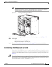
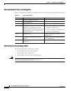
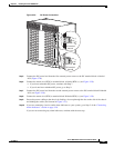
Step 6 Insert the stripped end of the grounding wire into the open end of a grounding lug and crimp the
grounding lug securely to the wire (see Figure 3-15).
Step 7 Attach the grounding lug to an appropriate grounding point at your site.
Step 8 Go to one of the following sections to continue the installation:
• If you are connecting DC power to the system, go to the “Connecting DC Power to the Cisco 10008
Router” section on page 3-17.
• If you are connecting AC power to the system, go to the “Connecting AC Power to the Cisco 10008
Router” section on page 3-22.
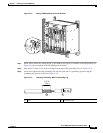
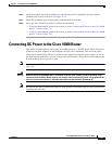
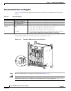
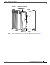
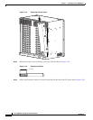
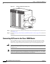
Connecting DC Power to the Cisco 10008 Router
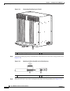
This section describes how to connect the Cisco 10008 router to a –48 VDC power source. The power
connectors are pillar terminals on the backplane. For full power redundancy, each set of DC power
connectors (terminal blocks labeled A and B) must be connected to separate power sources. If you do
not require power redundancy, you can use only one set of terminals—either the A terminal block or the
B terminal block. Do not use one of each.
Note If you are using AC PEMs, see the “Connecting a Video Terminal to the PRE Console Port” section on
page 3-30.
Warning
Before working on equipment that is connected to power lines, remove jewelry (including rings,
necklaces, and watches). Metal objects will heat up when connected to power and ground and the
heat can cause serious burns or weld the metal object to the terminals. Statement 43
Note Be sure that you have connected the chassis to earth ground as described in the previous section before
beginning this procedure.