


3-12
Cisco 10008 Router Hardware Installation Guide
OL-0659-13
Chapter 3 Installing the Cisco 10008 Router
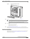
Non-Rack Installation
When installing the Cisco 10008 router on a workbench or tabletop, ensure that the surface is clean and
that you have considered the following:
• The Cisco 10008 router requires at least 3 inches (7.62 cm) of clearance at the inlet and exhaust
vents (the front and top/rear sides of the chassis).
• The Cisco 10008 router should be installed off the floor. Dust that accumulates on the floor is drawn
into the interior of the router by the cooling fans. Excessive dust inside the router can cause
overtemperature conditions and component failures.
• There must be approximately 19 inches (48.3 cm) of clearance at the front and rear of the chassis to
install and replace FRUs, or to access network cables and equipment.
• The Cisco 10008 router needs adequate ventilation. Do not install it in an enclosed cabinet where
ventilation is inadequate.
• Have the cable-management bracket available if you plan to install it on the front of the chassis.
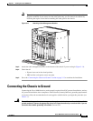
• An adequate chassis ground (earth) connection exists for your router chassis (see the “Connecting
the Chassis to Ground” section on page 3-13).
• Always follow proper lifting practices as outlined in the “Electrical Safety” section on page 2-13,
when handling the chassis.
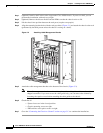
Use the following procedure to install the Cisco 10008 router on a tabletop or equipment shelf:
Step 1 Remove any debris and dust from the tabletop or equipment shelf, as well as the surrounding area.
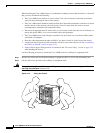
Step 2 Lift the chassis into position on the tabletop or equipment shelf.
Warning
Two people are required to lift the chassis. To prevent injury, keep your back straight and lift with
your legs, not your back.
Statement 164
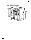
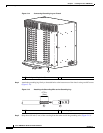
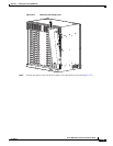
Figure 3-10 Lifting the Chassis
30007
1
3
2
4
0A
PROCESSOR ONLY
0B
5
6
7
8
PROCESSOR ONLY
P
O
W
E
R
F
A
U
L
T
M
I
S
W
I
R
E
P
O
W
E
R
F
A
U
L
T
M
I
S
W
I
R
E
C
IS
C
O
1
0
0
00
L
I
N
K
T
X
R
X
F
A
I
L
GIGABIT ETHERNET
CISCO
10000
C
A
R
R
I
E
R
A
L
A
R
M
L
O
O
P
F
A
I
L
CH OC-12-DSO SM-IR
C
I
S
C
O
1
0
0
0
0
CARRIER
ALARM
LOOP
F
A
I
L
6XCT3–DS0
0
5
4
3
2
1
C
I
S
C
O
1
0
0
0
0
CARRIER
ALARM
LOOP
F
A
I
L
6XCT3–DS0
0
5
4
3
2
1
F
A
I
L
PERFORMANCE ROUTING ENGINE
C
O
N
S
O
L
E
S
T
A
T
U
S
A
C
O
C
R
I
T
I
C
A
L
M
I
N
O
R
M
A
J
O
R
E
T
H
E
R
N
E
T
L
I
N
K
A
C
T
I
V
I
T
Y
A
U
X
S
L
O
T
0
S
L
O
T
1
F
A
I
L
PERFORMANCE ROUTING ENGINE
C
O
N
S
O
L
E
S
T
A
T
U
S
A
C
O
C
R
I
T
I
C
A
L
M
I
N
O
R
M
A
J
O
R
E
T
H
E
R
N
E
T
L
I
N
K
A
C
T
I
V
I
T
Y
A
U
X
S
L
O
T
0
S
L
O
T
1
C
I
S
C
O
1
0
0
0
0
CARRIE
R
ALARM
LOOP
F
A
I
L
6XCT3–DS0
0
5
4
3
2
1
C
I
S
C
O
1
0
0
0
0
C
ARRIER
AL
ARM
LOOP
F
A
I
L
6XCT3–DS0
0
5
4
3
2
1
C
I
S
C
O
1
0
0
0
0
CARR
IER
ALARM
LOOP
F
A
I
L
6XCT3–DS0
0
5
4
3
2
1
C
I
S
C
O
1
0
0
0
0
CARRIER
TX
RX
F
A
I
L
OC–12/STM–4 POS SM–IR
F
A
N
S
O
K
F
A
N
F
A
I
L
U
R
E
M
U
L
T
I
-
F
A
N
F
A
I
L
U
R
E
W
hen
hot s
w
app
ing this fa
n tra
y,
rem
ova
l an
d re
plac
em
ent m
ust
be do
ne in
under tw
o m
inu
tes
or
system s
hutdow
n w
ill occu
r.
C
A
UT
IO
N
C
I
S
C
O
1
0
0
0
0
C
I
S
C
O
1
0
0
0
0