


Chapter 3 Operating Principles | PCI-DMC-A01 / PCI-DMC-B01
Revised March, 2012 3-105
/* Set AD input range mode*/
rt =_DMC_01_set_04ad_input_range(gDMCCardNo,ADNodeID,SlotID,ChannelAD,
mode);
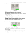
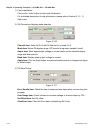
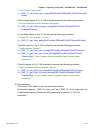
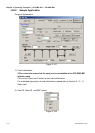
If the Average option in Fig. 3.139 is selected, execute the following procedure:
/* Set AD waveform output calculation frequency*/
rt =_DMC_01_set_04ad_average_mode(gDMCCardNo,ADNodeID,SlotID,
ChannelAD,mode);
For the Data display in Fig. 3.139, execute the following procedure:
/* Display AD input voltage or current */
rt =_DMC_01_get_04ad_data(gDMCCardNo,ADNodeID,SlotID,ChannelAD,data);
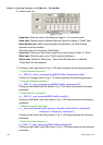
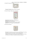
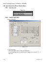
If the Zero option in Fig. 3.140 is selected, execute the following procedure:
/* Reset selected Channel */
rt =_DMC_01_set_04ad_zero_scale(gDMCCardNo,ADNodeID,SlotID,Channel);
rt =_DMC_01_get_04ad_zero_scale_status(gDMCCardNo,ADNodeID,SlotID,
Channel,flag); /* flag=1 means setup incomplete, flag=0 means setup
completed. */
If the Full option in Fig. 3.140 is selected, execute the following procedure:
/* Adjust maximum value of selected Channel */
rt =_DMC_01_set_04ad_full_scale(gDMCCardNo,ADNodeID,SlotID,Channel);
rt =_DMC_01_get_04ad_full_scale_status(gDMCCardNo,ADNodeID,SlotID,
Channel,flag); /* flag=1 means setup incomplete, flag=0 means setup
completed. */
8) Exit procedure
Click on the “Exit” button to quit and exit the procedure.
Exit function requires “_DMC_01_reset_card” and _DMC_01_close” to be used. For
a detailed description of these two API please refer to section 3.1.2 4) Exit
procedure.