


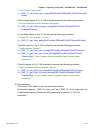

Chapter 3 Operating Principles | PCI-DMC-A01 / PCI-DMC-B01
Revised March, 2012 3-113
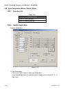
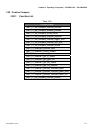
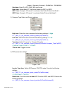
Card item: Enter ID of PCI_DMC_B01 card to use.
Node item: Select Node ID. This should match the QEP1 or QEP2.
QEP1 item: Example: If Channel 0 is selected, then Node ID should be Node 1.
QEP2 item: Example: If Channel 1 is selected, Node ID should be Node2.
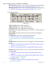
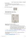
3) Compare Type Select and Polarity settings:
Figure 3.149
High item: Check this item to execute the following settings: 0: High
rt = _DMC_01_set_compare_channel_polarity(CpCardNo,0);
Low item: Check this item to execute the following settings: 1: Low
rt = _DMC_01_set_compare_channel_polarity(CpCardNo,1);
Type item: Select Compare1 or Compare2 function.
rt = _DMC_01_set_compare_channel_source(CpCardNo,Compare_Type,CpQEP);
//Compare_type:0=COMP1, 1=COMP2
TCount item: Trigger counter.
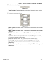
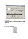
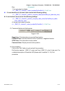
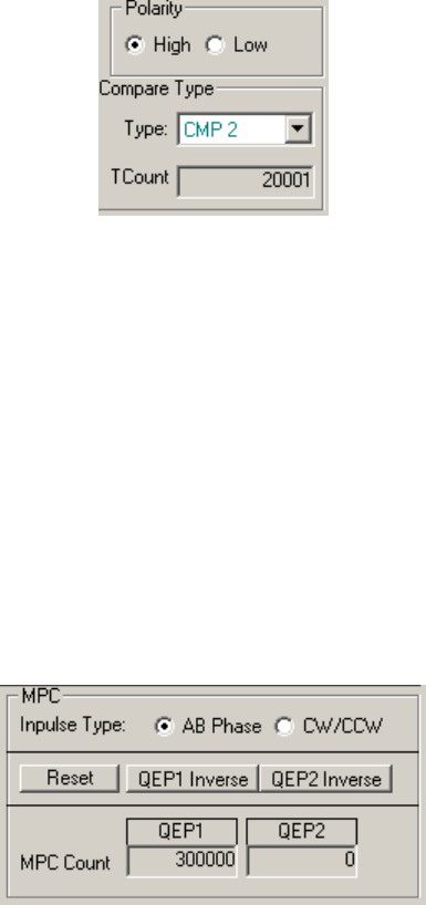
4) MPC parameter settings:
Figure 3.150
Inpulse Type item: Select AB Phase or CW/CCW mode. Execute the following
settings:
rt = _DMC_01_set_compare_ipulse_mode(CpCardNo,mode);
// 0: AB Phase 1: CW/CCW
Reset item: Click this button to clear MPC Count for QEP1 and QEP2. Execute the
following settings:
rt = _DMC_01_set_compare_channel_position(CpCardNo,channel,0);