


Chapter 4 Parameters|
Revision June 2008, 04EE, SW--PW V1.11/CTL V2.11 4-65
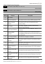
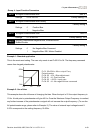
03.08 Fan Control
Factory Setting: 0
Settings 0 Fan always ON
1 1 minute after AC motor drive stops, fan will be OFF
2 Fan ON when AC motor drive runs, fan OFF when AC motor drive
stops
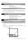
3 Fan ON when preliminary heatsink temperature attained
This parameter determines the operation mode of the cooling fan.
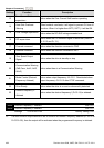
03.09
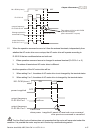
The Digital Output Used by PLC (NOT for VFD*E*C models)
Settings Read Only Factory setting: ##
Bit0=1: RLY used by PLC
Bit1=1: MO1 used by PLC
Bit2=1: MO2/RA2 used by PLC
Bit3=1: MO3/RA3 used by PLC
Bit4=1: MO4/RA4 used by PLC
Bit5=1: MO5/RA5 used by PLC
Bit6=1: MO6/RA6 used by PLC
Bit7=1: MO7/RA7 used by PLC
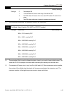
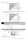
The equivalent 8-bit is used to display the status (used or not used) of each digital output. The
value that Pr.03.09 displays is the result after converting 8-bit binary into decimal value.
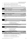
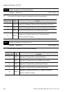
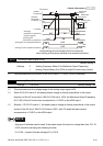
For standard AC motor drive, it only has 2-bit (bit0 and bit1). When extension card is installed,
the number of the digital output terminals will increase according to the extension card. The
maximum number of the digital output terminals is shown as follows.