


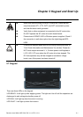

Chapter 2 Installation and Wiring|
2-18 Revision June 2008, 04EE, SW--PW V1.11/CTL V2.11
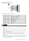
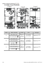
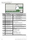
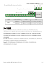
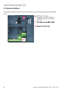
The position of the control terminals
RS-485
10VMI1 MI2 MI3 MI4 MI5 MI6
DCM
24V
DCM ACM
AVI ACI
AFM MCM MO1
RA
RB RC
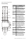
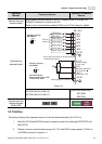
Terminal symbols and functions
Terminal
Symbol
Terminal Function
Factory Settings (NPN mode)
ON: Connect to DCM
MI1 Forward-Stop command
ON: Run in MI1 direction
OFF: Stop acc. to Stop Method
MI2 Reverse-Stop command
ON: Run in MI2 direction
OFF: Stop acc. to Stop Method
MI3 Multi-function Input 3
MI4 Multi-function Input 4
MI5 Multi-function Input 5
MI6 Multi-function Input 6
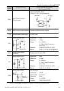
Refer to Pr.04.05 to Pr.04.08 for programming the
Multi-function Inputs.
ON: the activation current is 5.5mA.
OFF: leakage current tolerance is 10
μ
A.
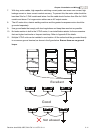
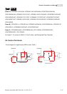
+24V DC Voltage Source +24VDC, 20mA used for PNP mode.
DCM Digital Signal Common
Common for digital inputs and used for NPN
mode.
RA
Multi-function Relay output
(N.O.) a
RB
Multi-function Relay output
(N.C.) b
RC Multi-function Relay common
Resistive Load:
5A(N.O.)/3A(N.C.) 240VAC
5A(N.O.)/3A(N.C.) 24VDC
Inductive Load:
1.5A(N.O.)/0.5A(N.C.) 240VAC
1.5A(N.O.)/0.5A(N.C.) 24VDC
Refer to Pr.03.00 for programming