


Chapter 4 Parameters|
4-122 Revision June 2008, 04EE, SW--PW V1.11/CTL V2.11
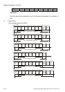
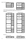
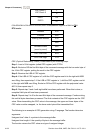
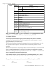
‘F’ LRC Check 1
LRC Check 0
‘6’
CR END 1
END 0
LF
01H+03H+04H+01H+00H+01H=0AH, the 2’s-complement negation of 0AH is F6H.
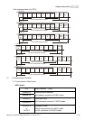
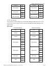
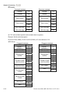
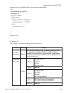
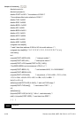
RTU mode:
Address
01H
Function 03H
21H Starting data address
02H
00H Number of data
(count by word)
02H
CRC CHK Low 6FH
CRC CHK High F7H
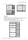
CRC (Cyclical Redundancy Check) is calculated by the following steps:
Step 1: Load a 16-bit register (called CRC register) with FFFFH.
Step 2: Exclusive OR the first 8-bit byte of the command message with the low order byte of
the 16-bit CRC register, putting the result in the CRC register.
Step 3: Examine the LSB of CRC register.
Step 4: If the LSB of CRC register is 0, shift the CRC register one bit to the right with MSB
zero filling, then repeat step 3. If the LSB of CRC register is 1, shift the CRC register one bit
to the right with MSB zero filling, Exclusive OR the CRC register with the polynomial value
A001H, then repeat step 3.
Step 5: Repeat step 3 and 4 until eight shifts have been performed. When this is done, a
complete 8-bit byte will have been processed.
Step 6: Repeat step 2 to 5 for the next 8-bit byte of the command message. Continue doing
this until all bytes have been processed. The final contents of the CRC register are the CRC
value. When transmitting the CRC value in the message, the upper and lower bytes of the
CRC value must be swapped, i.e. the lower order byte will be transmitted first.
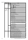
The following is an example of CRC generation using C language. The function takes two
arguments:
Unsigned char* data Å a pointer to the message buffer
Unsigned char length Å the quantity of bytes in the message buffer
The function returns the CRC value as a type of unsigned integer.