


Chapter 4 Parameters|
Revision June 2008, 04EE, SW--PW V1.11/CTL V2.11 4-125
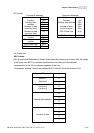
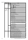
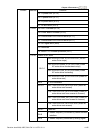
Content Address Function
24: U-phase error (cF3.0)
25: V-phase error (cF3.1)
26: W-phase error (cF3.2)
27: DCBUS error (cF3.3)
2100H 28: IGBT Overheat (cF3.4)
29: Power Board Overheat (cF3.5)
30: Control Board CPU WRITE failure (cF1.1)
31: Control Board CPU WRITE failure (cF2.1)
32: ACI signal error (AErr)
33: Reserved
34: Motor PTC overheat protection (PtC1)
Status of AC drive
00B: RUN LED is off, STOP LED is on (The AC
motor Drive stops)
01B: RUN LED blinks, STOP LED is on (When
AC motor drive decelerates to stop)
10B: RUN LED is on, STOP LED blinks (When
AC motor drive is standby)
Bit 0-1
11B: RUN LED is on, STOP LED is off (When AC
motor drive runs)
Bit 2 1: JOG command
Bit 3-4 00B: FWD LED is on, REV LED is off (When AC
motor drive runs forward)
01B: FWD LED is on, REV LED blinks (When AC
motor drive runs from reverse to forward)
10B: FWD LED blinks, REV LED is on (When AC
motor drive runs from forward to reverse)
11B: FWD LED is off, REV LED is on (When AC
motor drive runs reverse)
Bit 5-7 Reserved
Bit 8
1: Master frequency Controlled by communication
interface
2101H
Bit 9 1: Master frequency controlled by analog signal