


Appendix D How to Use PLC Function|
Revision June 2008, 04EE, SW--PW V1.11/CTL V2.11 D-15
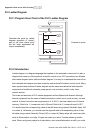
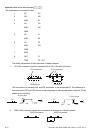
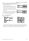
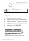
Example 3: the latching circuit of SET and RST commands
SET
Y1
RST
Y1
X1
X2
Top priority of stop
The figure at the right side is latching circuit that made
up of RST and SET command.
It is top priority of stop when RST command is set
behind SET command. When executing PLC from up
to down, The coil Y1 is ON and coil Y1 will be OFF
when X1 and X2 act at the same time, therefore it calls
priority of stop.
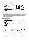
It is top priority of start when SET command is set after
RST command. When X1 and X2 act at the same
time, Y1 is ON so it calls top priority of start.
SET
Y1
RST
Y1
X2
X1
Top priority of start
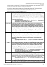
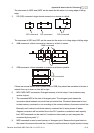
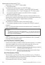
The common control circuit
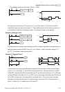
Example 4: condition control
X3
Y1
X1
Y1
X4
Y2
X2
Y2
Y1
X1
X3
X2
X4
Y1
Y2
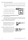
X1 and X3 can start/stop Y1 separately, X2 and X4 can start/stop Y2 separately and they are all
self latched circuit. Y1 is an element for Y2 to do AND function due to the normally open contact
connects to Y2 in series. Therefore, Y1 is the input of Y2 and Y2 is also the input of Y1.