


Appendix D How to Use PLC Function|
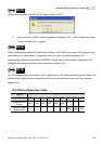
Revision June 2008, 04EE, SW--PW V1.11/CTL V2.11 D-11
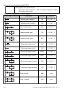
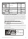
Ladder Diagram Structure Explanation Command Equipment
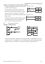
Multiple output
MPS
MRD
MPP
none
Output command of coil drive OUT Y, M, S
Basic command, Application
command
Application
command
Please refer to
basic command
and application
command
Inverse logic INV none
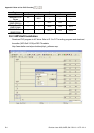
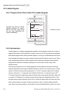
D.3.3 The Edition of PLC Ladder Diagram
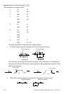
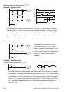
The program edited method is from left power line to right power line. (the right power line
will be omitted during the edited of WPLSoft.) After editing a row, go to editing the next row.
The maximum contacts in a row are 11 contacts. If you need more than 11 contacts, you
could have the new row and start with continuous line to continue more input devices. The
continuous number will be produced automatically and the same input point can be used
repeatedly. The drawing is shown as follows.
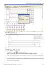
X0 X1 X2 X3 X4 X5
Y0
X11 X12 X13
X6 X7 X10 C0 C1
00000
00000
Row Number
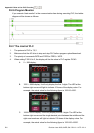
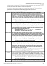
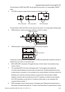
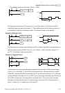
The operation of ladder diagram is to scan from left upper corner to right lower corner. The
output handling, including the operation frame of coil and application command, at the most
right side in ladder diagram.
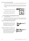
Take the following diagram for example; we analyze the process step by step. The number
at the right corner is the explanation order.
X0 X1 Y1 X4
M0
X3
M1
T0
M3
Y1
TMR T0 K10