


Chapter 4 Parameters|
4-30 Revision June 2008, 04EE, SW--PW V1.11/CTL V2.11
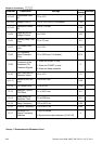
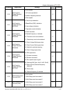
Parameter Explanation Settings
Factory
Setting
Customer
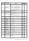
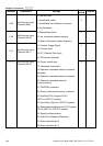
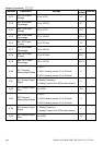
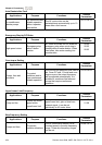
12.12
Min. AVI4 Input
Voltage
0.0 to 10.0V 0.0
12.13
Min. AVI4 Scale
Percentage
0.0 to 100.0% 0.0
12.14
Max. AVI4 Input
Voltage
0.0 to 10.0V 10.0
12.15
Max. AVI4 Scale
Percentage
0.0 to 100.0% 100.0
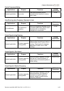
12.16
Min. ACI3 Input
Current
0.0 to 20.0mA 4.0
12.17
Min. ACI3 Scale
Percentage
0.0 to 100.0% 0.0
12.18
Max. ACI3 Input
Current
0.0 to 20.0mA 20.0
12.19
Max. ACI3 Scale
Percentage
0.0 to 100.0% 100.0
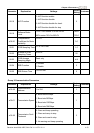
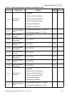
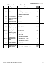
0: AVO1
1: ACO1 (analog current 0.0 to 20.0mA)
12.20
AO1 Terminal
Analog Signal Mode
2: ACO1 (analog current 4.0 to 20.0mA)
0
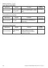
0: Analog Frequency
12.21
AO1 Analog Output
Signal
1: Analog Current (0 to 250% rated current)
0
12.22
AO1 Analog Output
Gain
1 to 200% 100
0: AVO2
1: ACO2 (analog current 0.0 to 20.0mA)
12.23
AO2 Terminal
Analog Signal Mode
2: ACO2 (analog current 4.0 to 20.0mA)
0
0: Analog Frequency
12.24
AO2 Analog Output
Signal
1: Analog Current (0 to 250% rated current)
0
12.25
AO2 Analog Output
Gain
1 to 200% 100