


Chapter 4 Parameters|
Revision June 2008, 04EE, SW--PW V1.11/CTL V2.11 4-147
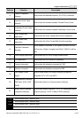
12.20
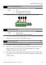
AO1 Terminal Analog Signal Mode
Factory Setting: 0
Settings 0 AVO1
1 ACO1 (analog current 0.0 to 20.0mA)
2 ACO1 (analog current 4.0 to 20.0mA)
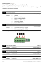
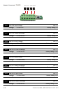
Besides parameter setting, the voltage/current mode should be used with the switch.
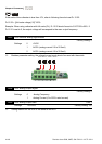
AVI3
ACI2
AVI4
ACI3
AVO1
ACO1
AVO2
ACO2
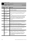
12.21
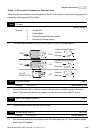
AO1 Analog Output Signal
Factory Setting: 0
Settings 0 Analog Frequency
1 Analog Current (0 to 250% rated current)
This parameter is used to choose analog frequency (0-+10Vdc) or analog current (4-20mA) to
correspond to the AC motor drive’s output frequency or current.
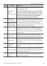
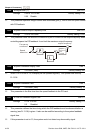
12.22 AO1 Analog Output Gain Unit: 1
Settings 1 to 200% Factory Setting: 100
This parameter is used to set the analog output voltage range.
When Pr.12.21 is set to 0, analog output voltage corresponds to the AC motor drive’s output
frequency. When Pr.12.22 is set to 100, the max. output frequency (Pr.01.00) setting
corresponds to the AFM output (+10VDC or 20mA)
When Pr.12.21 is set to 1, analog output voltage corresponds to the AC motor drive’s output
current. When Pr.12.22 is set to 100, the 2.5 X rated current corresponds to the AFM output
(+10VDC or 20mA)