


Chapter 1 Introduction|
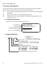
1-4 Revision June 2008, 04EE, SW--PW V1.11/CTL V2.11
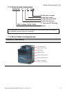
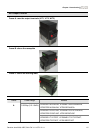
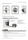
1-15HP/0.75-11kW (Frame B&C)
Input terminals cover
(R/L1, S/L2, T/L3)
Case body
Keypad cover
Output terminals cover
(U/T1, V/T2, W/T3)
Control board cover
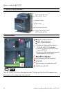
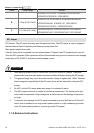
Internal Structure
1.
2.
3.
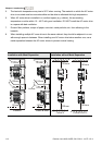
READY: power indicator
RUN: status indicator
FAULT: fault indicator
NPN/PNP
RS485 port (RJ-45)
Switch to ON for 50Hz, refer to
P 01.00 to P01.02 for details
Switch to ON for free run to stop
refer to P02.02
Switch to ON for setting frequency
source to ACI (P 02.00=2)
ACI terminal (ACI/AVI2 switch )
Mounting port for extension card
NOTE
The LED “READY” will light up after applying power. The light won’t be off until the capacitors are
discharged to safe voltage levels after power off.