


Chapter 4 Parameters|
Revision June 2008, 04EE, SW--PW V1.11/CTL V2.11 4-83
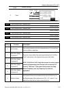
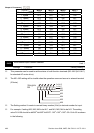
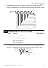
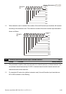
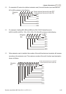
When extension card is installed, the number of the digital input terminals will increase
according to the extension card. The maximum number of the digital input terminals is shown
as follows.
12345 0
MI1
MI2
MI3
MI4
MI5
MI6
Weights
Bit
7891011 6
MI7
MI8
MI9
MI10
MI11
MI12
0=not used
1=Used by PLC
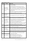
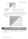
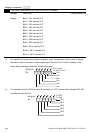
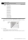
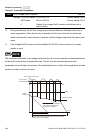
04.25 The Analog Input Used by PLC (NOT for VFD*E*C models)
Settings Read Only Factory setting: ##
Display Bit0=1: AVI used by PLC
Bit1=1: ACI/AVI2 used by PLC
Bit2=1: AI1 used by PLC
Bit3=1: AI2 used by PLC
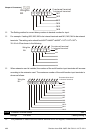
The equivalent 2-bit is used to display the status(used or not used) of each analog input. The
value for Pr.04.25 to display is the result after converting 2-bit binary into decimal value.
1
0
Weights
Bit
0=not used
1=used by PLC
AVI
ACI/AVI2
13
2
AI1 (optional)
AI2 (optional)