


Chapter 4 Parameters|
4-96 Revision June 2008, 04EE, SW--PW V1.11/CTL V2.11
Group 7: Motor Parameters
07.00 Motor Rated Current (Motor 0) Unit: 1
Settings 30% FLA to 120% FLA Factory Setting: FLA
Use the following formula to calculate the percentage value entered in this parameter:
(Motor Current / AC Drive Current) x 100%
with Motor Current=Motor rated current in A on type shield
AC Drive Current=Rated current of AC drive in A (see Pr.00.01)
Pr.07.00 and Pr.07.01 must be set if the drive is programmed to operate in Vector Control
mode (Pr.00.10 = 1). They also must be set if the "Electronic Thermal Overload Relay"
(Pr.06.06) or "Slip Compensation"(Pr.07-03) functions are selected.
Pr.07.00 must be greater than Pr.07.01.
07.01
Motor No-load Current (Motor 0)
Unit: 1
Settings 0% FLA to 90% FLA Factory Setting: 0.4*FLA
The rated current of the AC drive is regarded as 100%. The setting of the Motor no-load
current will affect the slip compensation.
The setting value must be less than Pr.07.00 (Motor Rated Current).
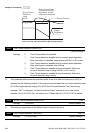
07.02 Torque Compensation (Motor 0) Unit: 0.1
Settings 0.0 to 10.0 Factory Setting: 0.0
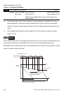
This parameter may be set so that the AC drive will increase its voltage output to obtain a
higher torque. Only to be used for V/f control mode.
Too high torque compensation can overheat the motor.
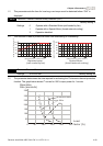
07.03 Slip Compensation (Used without PG) (Motor 0) Unit: 0.01
Settings 0.00 to 10.00 Factory Setting: 0.00
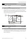
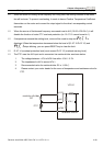
While driving an asynchronous motor, increasing the load on the AC motor drive will cause an
increase in slip and decrease in speed. This parameter may be used to compensate the slip by
increasing the output frequency. When the output current of the AC motor drive is bigger than
the motor no-load current (Pr.07.01), the AC drive will adjust its output frequency according to
this parameter.