


Chapter 4 Parameters|
4-112 Revision June 2008, 04EE, SW--PW V1.11/CTL V2.11
Group 9: Communication Parameters
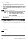
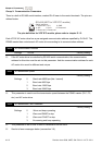
There is a built-in RS-485 serial interface, marked RJ-45 near to the control terminals. The pins are
defined below:
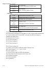
RS-485 (NOT for VFD*E*C models)
Serial interface
1: Reserved 2: EV
5: SG+ 6: Reserved
7: Reserved 8: Reserved
3: GND
4: SG-
8
1
The pins definition for VFD*E*C models, please refer to chapter E.1.2.
Each VFD-E AC motor drive has a pre-assigned communication address specified by Pr.09.00. The
RS485 master then controls each AC motor drive according to its communication address.
09.00 Communication Address
Settings 1 to 254 Factory Setting: 1
If the AC motor drive is controlled by RS-485 serial communication, the communication
address for this drive must be set via this parameter. And the communication address for each
AC motor drive must be different and unique.
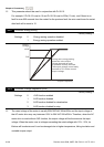
09.01 Transmission Speed
Factory Setting: 1
Settings 0 Baud rate 4800 bps (bits / second)
1 Baud rate 9600 bps
2 Baud rate 19200 bps
3 Baud rate 38400 bps
This parameter is used to set the transmission speed between the RS485 master (PLC, PC,
etc.) and AC motor drive.
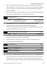
09.02 Transmission Fault Treatment
Factory Setting: 3
Settings 0 Warn and keep operating
1 Warn and RAMP to stop
2 Warn and COAST to stop
3 No warning and keep operating
This parameter is set to how to react if transmission errors occur.
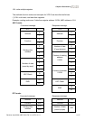
See list of error messages below (see section 3.6.)