


Chapter 2 Installation and Wiring|
2-14 Revision June 2008, 04EE, SW--PW V1.11/CTL V2.11
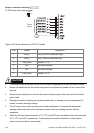
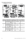
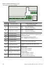
Terminal Symbol Explanation of Terminal Function
R/L1, S/L2, T/L3
AC line input terminals (1-phase/3-phase)
U/T1, V/T2, W/T3
AC drive output terminals for connecting 3-phase induction motor
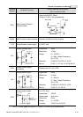
+/B1~ B2
Connections for Brake resistor (optional)
+/B1, -
Connections for External Brake unit (BUE series)
Earth connection, please comply with local regulations.
CAUTION!
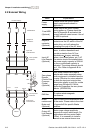
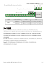
Mains power terminals (R/L1, S/L2, T/L3)
Connect these terminals (R/L1, S/L2, T/L3) via a no-fuse breaker or earth leakage breaker
to 3-phase AC power (some models to 1-phase AC power) for circuit protection. It is
unnecessary to consider phase-sequence.
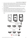
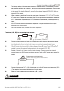
It is recommended to add a magnetic contactor (MC) in the power input wiring to cut off
power quickly and reduce malfunction when activating the protection function of AC motor
drives. Both ends of the MC should have an R-C surge absorber.
Please make sure to fasten the screw of the main circuit terminals to prevent sparks
which is made by the loose screws due to vibration.
Please use voltage and current within the regulation shown in Appendix A.
When using a general GFCI (Ground Fault Circuit Interrupter), select a current sensor
with sensitivity of 200mA or above, and not less than 0.1-second operation time to avoid
nuisance tripping. For the specific GFCI of the AC motor drive, please select a current
sensor with sensitivity of 30mA or above.
Do NOT run/stop AC motor drives by turning the power ON/OFF. Run/stop AC motor
drives by RUN/STOP command via control terminals or keypad. If you still need to
run/stop AC drives by turning power ON/OFF, it is recommended to do so only ONCE per
hour.
Do NOT connect 3-phase models to a 1-phase power source.
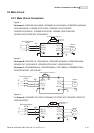
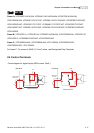
Output terminals for main circuit (U, V, W)