


Chapter 2 Installation and Wiring|
Revision June 2008, 04EE, SW--PW V1.11/CTL V2.11 2-7
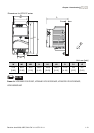
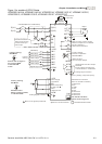
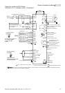
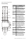
Figure 5 for models of VFD-E Series
VFD002E11T/21T, VFD004E11A/21T, VFD007E21T
AVI
ACI
ACM
B1
+10V
5K
3
2
1
Power supply
+10V 20mA
Master Frequency
0 to 10V 47K
Analog Signal Common
E
Main circuit (power) terminals
Control circuit terminals
Shielded leads & Cable
E
R(L1)
S(L2)
Fuse/NFB(No Fuse Breaker)
SA
OFF
ON
MC
MC
RB
RC
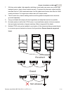
Recommended Circuit
when power supply
is turned OFF by a
fault output
R(L1)
S(L2)
E
Analog Multi-function
Output Terminal
factory setting: Analog
freq./ current meter
0~10VDC/2mA
U(T1)
V(T2)
W(T3)
IM
3~
AFM
ACM
RA
RB
RC
Motor
Factory setting:
Drive is in operation
48V50mA Max.
Multi-function
Photocoulper Output
Analog Signal common
E
E
MO1
MCM
MI1
MI2
MI3
MI4
MI6
MI5
DCM
+24V
FWD/Stop
REV/Stop
Multi-step 1
Multi-step 2
Multi-step 3
Multi-step 4
Digital Signal Common
Factory
setting
Sw2
AVI
ACI
Factory setting:
ACI Mode
ACI/AVI switch
When switching to AVI,
it indicates AVI2
B2
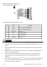
RS-485
Serial interface
1: Reserved
2: EV
5: SG+
6: Reserved
7: Reserved
8: Reserved
3: GND
4: SG-
8
1
Sw1
NPN
PNP
Factory setting:
NPN Mode
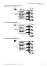
Please refer to Figure 7
for wiring of NPN
mode and PNP
mode.
BR
brake resistor
(optional)
Multi-function contact output
Refer to chapter2.4 for details.
Factory setting is
malfunction indication
Factory setting: output
frequency
4-20mA/0-10V
NOTE
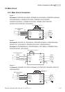
For VFD-E-T series, the braking resistor can be used by connecting terminals (B1 and B2) directly. But
it can't connect DC-BUS in parallel.