


Appendix D How to Use PLC Function|
Revision June 2008, 04EE, SW--PW V1.11/CTL V2.11 D-3
NOTE
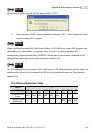
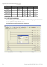
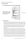
When power on after power off, the PLC status will be in “PLC1”.
4. When you are in “PLC2”, please remember to change to “PLC1” when finished to prevent
anyone modifying PLC program.
NOTE
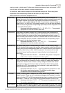
When output/input terminals (MI1~MI9, Relay1~Relay 4, MO1~MO4) are used in PLC program, they
cannot be used in other places. For example, When Y0 in PLC program is activated, the
corresponding output terminals Relay (RA/RB/RC) will be used. At this moment, parameter 03.00
setting will be invalid. Because the terminal has been used by PLC.
NOTE
The PLC corresponding input points for MI1 to MI6 are X0 to X5. When extension card are added, the
extension input points will be numbered from X06 and output points will start from Y2 as shown in
chapter D.2.2.
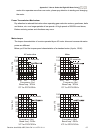
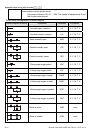
D.2.2 Device Reference Table
Device X
ID 0 1 2 3 4 5 6 7 10
Terminals of AC
Drives
MI1 MI2 MI3 MI4 MI5 MI6 -- -- --
3IN/3OUT Card
(EME-D33A)
-- -- -- -- -- -- MI7 MI8 MI9