


Chapter 2 Installation and Wiring|
2-20 Revision June 2008, 04EE, SW--PW V1.11/CTL V2.11
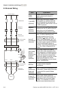
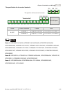
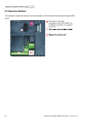
Analog inputs (AVI, ACI, ACM)
Analog input signals are easily affected by external noise. Use shielded wiring and keep it
as short as possible (<20m) with proper grounding. If the noise is inductive, connecting
the shield to terminal ACM can bring improvement.
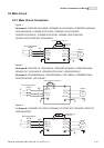
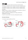
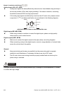
If the analog input signals are affected by noise from the AC motor drive, please connect
a capacitor (0.1
μ
F and above) and ferrite core as indicated in the following diagrams:
C
A
VI/ACI
ACM
ferrite core
wind each wires 3 times or more around the core
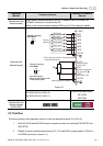
Digital inputs (MI1~MI6, DCM)
When using contacts or switches to control the digital inputs, please use high quality
components to avoid contact bounce.
Digital outputs (MO1, MCM)
Make sure to connect the digital outputs to the right polarity, see wiring diagrams.
When connecting a relay to the digital outputs, connect a surge absorber or fly-back diode
across the coil and check the polarity.
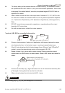
General
Keep control wiring as far away as possible from the power wiring and in separate
conduits to avoid interference. If necessary let them cross only at 90º angle.
The AC motor drive control wiring should be properly installed and not touch any live
power wiring or terminals.
DANGER!
Damaged insulation of wiring may cause personal injury or damage to circuits/equipment if it comes
in contact with high voltage.