


Chapter 4 Parameters|
Revision June 2008, 04EE, SW--PW V1.11/CTL V2.11 4-101
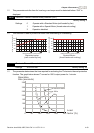
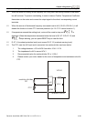
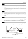
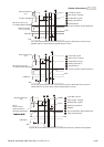
If temperature exceeds the motor PTC overheat warning level (Pr.07.15), the drive will act
according to Pr.07.17 and display
. If the temperature decreases below the result
(Pr.07.15 minus Pr.07.16), the warning display will disappear.
07.13 Input Debouncing Time of the PTC Protection Unit: 2
Settings 0~9999 (is 0-19998ms) Factory Setting: 100
This parameter is to delay the signals on PTC analog input terminals. 1 unit is 2 msec, 2 units
are 4 msec, etc.
07.18 Motor Rated Current (Motor 1) Unit: 1
Settings 30% FLA to 120% FLA Factory Setting: FLA
07.19
Motor No-load Current (Motor 1)
Unit: 1
Settings 0% FLA to 90% FLA Factory Setting: 0.4*FLA
07.20 Torque Compensation (Motor 1) Unit: 0.1
Settings 0.0 to 10.0 Factory Setting: 0.0
07.21 Slip Compensation (Used without PG) (Motor 1) Unit: 0.01
Settings 0.00 to 10.00 Factory Setting: 0.00
07.22 Motor Line-to-line Resistance R1 (Motor 1) Unit: 1
Settings
0 to 65535 mΩ
Factory Setting: 0
07.23 Motor Rated Slip (Motor 1) Unit: 0.01
Settings 0.00 to 20.00Hz Factory Setting: 3.00
07.24 Motor Pole Number (Motor 1) Unit: 1
Settings 2 to 10 Factory Setting: 4
07.25 Motor Rated Current (Motor 2) Unit: 1
Settings 30% FLA to 120% FLA Factory Setting: FLA
07.26
Motor No-load Current (Motor 2)
Unit: 1
Settings 0% FLA to 90% FLA Factory Setting: 0.4*FLA
07.27 Torque Compensation (Motor 2) Unit: 0.1
Settings 0.0 to 10.0 Factory Setting: 0.0
07.28 Slip Compensation (Used without PG) (Motor 2) Unit: 0.01
Settings 0.00 to 10.00 Factory Setting: 0.00
07.29 Motor Line-to-line Resistance R1 (Motor 2) Unit: 1
Settings
0 to 65535 mΩ
Factory Setting: 0
07.30 Motor Rated Slip (Motor 2) Unit: 0.01
Settings 0.00 to 20.00Hz Factory Setting: 3.00