


Appendix D How to Use PLC Function|
D-22 Revision June 2008, 04EE, SW--PW V1.11/CTL V2.11
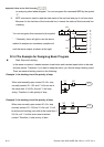
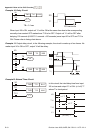
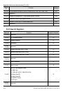
External output: Y0~Y7, Y10~Y17…(device number)
3. Decimal Number (DEC)
The suitable time for decimal number to use in DVP-PLC system.
To be the setting value of timer T or counter C, such as TMR C0 K50. (K constant)
To be the device number of M, T, C and D. For example: M10, T30. (device number)
To be operand in application command, such as MOV K123 D0. (K constant)
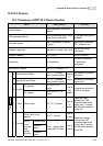
4. BCD (Binary Code Decimal, BCD)
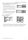
It shows a decimal number by a unit number or four bits so continuous 16 bits can use to
represent the four numbers of decimal number. BCD code is usually used to read the input
value of DIP switch or output value to 7-segment display to be display.
5. Hexadecimal Number (HEX)
The suitable time for hexadecimal number to use in DVP-PLC system.
To be operand in application command. For example: MOV H1A2B D0. (constant H)
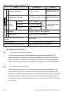
Constant K:
In PLC, it is usually have K before constant to mean decimal number. For example, K100
means 100 in decimal number.
Exception:
The value that is made up of K and bit equipment X, Y, M, S will be bit, byte, word or
double word. For example, K2Y10, K4M100. K1 means a 4-bit data and K2~K4 can
be 8, 12 and 16-bit data separately.
Constant H:
In PLC, it is usually have H before constant to mean hexadecimal number. For example,
H100 means 100 in hexadecimal number.
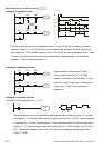
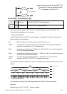
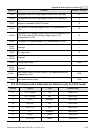
D.4.4 The Function of Auxiliary Relay
There are output coil and A, B contacts in auxiliary relay M and output relay Y. It is unlimited
usage times in program. User can control loop by using auxiliary relay, but can’t drive
external load directly. There are two types divided by its characteristics.
1. Auxiliary relay for general : It will reset to Off when power loss during running. Its state will
be Off when power on after power loss.
2. Auxiliary relay for special : Each special auxiliary relay has its special function. Please
don’t use undefined auxiliary relay.
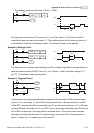
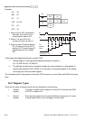
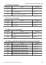
D.4.5 The Function of Timer
The unit of timer is 1ms, 10ms and 100ms. The count method is count up. The output coil
will be On when the present value of timer equals to the settings. The setting is K in decimal
number. Data register D can be also used as settings.
The real setting time of timer = unit of timer * settings