


Chapter 4 Parameters|
4-66 Revision June 2008, 04EE, SW--PW V1.11/CTL V2.11
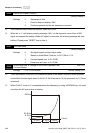
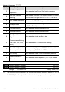
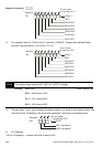
1 0
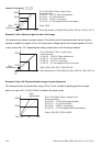
Weights
Bit
Relay 1
MO1
3 25 47 6
MO2/RA2
MO3/RA3
MO4/RA4
MO5/RA5
MO6/RA6
MO7/RA7
0=not used
1=Used by PLC
For example: when Pr.03.09 is set to 3 (decimal) = 00000011 (binary) that indicates Relay1
and MO1 are used by PLC. (Pr.03.09= 2
0
+2
1
=3)
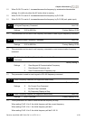
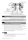
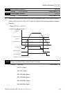
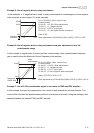
1 1
Weights
Bit
Relay 1
MO1
0 00 00 0
MO2/RA2
MO3/RA3
MO4/RA4
MO5/RA5
MO6/RA6
MO7/RA7
0=not used
1=Used by PLC
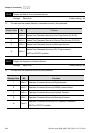
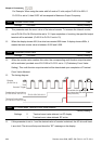
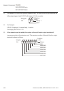
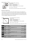
03.10 The Analog Output Used by PLC (NOT for VFD*E*C models)
Settings Read Only Factory setting: ##
Bit0=1: AFM used by PLC
Bit1=1: AO1 used by PLC
Bit2=1: AO2 used by PLC
The equivalent 1-bit is used to display the status (used or not used) of each analog output. The
value that Pr.03.10 displays is the result after converting 1-bit binary into decimal value.
0
Weights
Bit
0=not used
1=Used by PLC
AFM
12
AO1 (optional)
AO2 (optional)
For Example:
If Pr.03.10 displays 1, it means that AFM is used by PLC.