


Chapter 2 Installation and Wiring|
2-10 Revision June 2008, 04EE, SW--PW V1.11/CTL V2.11
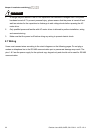
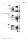
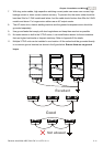
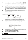
D. PNP mode with external power
Sw1
Factory
setting
NPN
PNP
24
Vdc
-
+
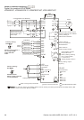
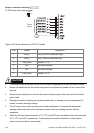
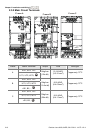
Figure 8 RJ-45 pin definition for VFD*E*C models
PIN Signal Description
1 CAN_H CAN_H bus line (dominant high)
2 CAN_L CAN_L bus line (dominant low)
3 CAN_GND Ground / 0V /V-
4 SG+ 485 communication
5 SG- 485 communication
7 CAN_GND Ground / 0V /V-
CAUTION!
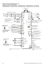
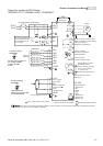
1. The wiring of main circuit and control circuit should be separated to prevent erroneous actions.
2. Please use shield wire for the control wiring and not to expose the peeled-off net in front of the
terminal.
3. Please use the shield wire or tube for the power wiring and ground the two ends of the shield
wire or tube.
4. Damaged insulation of wiring may cause personal injury or damage to circuits/equipment if it
comes in contact with high voltage.
5. The AC motor drive, motor and wiring may cause interference. To prevent the equipment
damage, please take care of the erroneous actions of the surrounding sensors and the
equipment.
6. When the AC drive output terminals U/T1, V/T2, and W/T3 are connected to the motor terminals
U/T1, V/T2, and W/T3, respectively. To permanently reverse the direction of motor rotation,
switch over any of the two motor leads.