


Chapter 4 Parameters|
Revision June 2008, 04EE, SW--PW V1.11/CTL V2.11 4-3
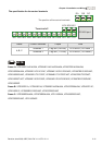
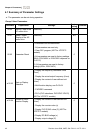
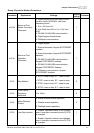
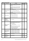
Parameter Explanation Settings
Factory
Setting
Customer
5: Display PID analog feedback signal value
(b) (%)
6: Output power factor angle (n)
7: Display output power (P)
8: Display the estimated value of torque as it
relates to current (t)
9: Display AVI (I) (V)
10: Display ACI / AVI2 (i) (mA/V)
11: Display the temperature of IGBT (h) (°C)
12: Display AVI3/ACI2 level (I.)
13: Display AVI4/ACI3 level (i.)
14: Display PG speed in RPM (G)
15: Display motor number (M)
00.05
User-Defined
Coefficient K
0. 1 to 160.0 1.0
00.06 Power Board
Software Version
Read-only #.##
00.07 Control Board
Software Version
Read-only #.##
00.08 Password Input 0 to 9999 0
00.09 Password Set 0 to 9999 0
0: V/f Control
00.10 Control Method
1: Vector Control
0
00.11 Reserved
00.12
50Hz Base Voltage
Selection
0: 230V/400V
1: 220V/380V
0
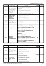
Group 1 Basic Parameters
Parameter Explanation Settings
Factory
Setting
Customer
01.00
Maximum Output
Frequency (Fmax)
50.00 to 600.0 Hz 60.00