


Chapter 4 Parameters|
Revision June 2008, 04EE, SW--PW V1.11/CTL V2.11 4-149
Group 13: PG function Parameters for Extension Card
Make sure that the extension card is installed on the AC motor drive correctly before using group 12
parameters. See Appendix B for details.
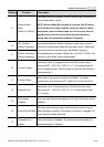
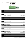
13.00 PG Input
Factory Setting: 0
Settings 0 Disable PG
1 Single phase
2 Forward/Counterclockwise rotation
3 Reverse/Clockwise rotation
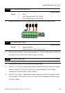
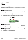
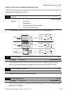
The relationship between the motor rotation and PG input is illustrated below:
FWD
CCW
REV
CW
PULSE
GENERATOR
PG
13.00=2
13.00=3
A phase leads B phase
A phase
A phase
A phase
B phase
B phase
B phase
CW
B phase leads A phase
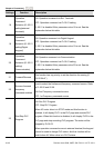
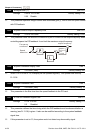
13.01 PG Pulse Range Unit: 1
Settings 1 to 20000 Factory Setting: 600
A Pulse Generator (PG) is used as a sensor that provides a feedback signal of the motor
speed. This parameter defines the number of pulses for each cycle of the PG control.
13.02 Motor Pole Number (Motor 0) Unit: 1
Settings 2 to 10 Factory Setting: 4
The pole number should be even (can’t be odd).
13.03 Proportional Gain (P) Unit: 0.01
Settings 0.0 to 10.0 Factory Setting: 1.0
This parameter specifies proportional control and associated gain (P), and is used for speed
control with PG feedback.