


INTELLIGENT DISPATCH MODULE (IDM)
12-2
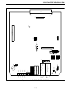
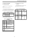
12.2 IDM SETUP PROCEDURE
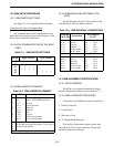
12.2.1 SWITCH SETTINGS
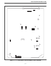
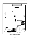
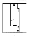
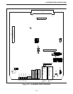
Refer to Figure 12-2 for Alignment Points
Diagram.
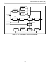
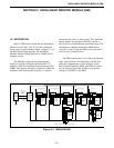
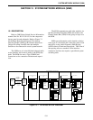
Command and Control Communication
The command and control communication to the
Consoles takes place on a digital RS-232 link at 9600
baud. The digital link occurs on the Secondary lines.
12.2.2 IDM JUMPER PLACEMENT
12.2.3 IDM BACKPLANE EXTERNAL
CONTACTS
See the Backplane Section 23 for pinouts on the
shelf backplane and wire harness pinouts.
Table 12-1 IDM SWITCH SETTINGS
Switch Open Sections Close Sections
S1
S3
S4
S5
1
1
-
-
2
2
-
-
-
-
3
-
4
-
4
-
-
-
1
1
-
-
2
2
3
3
-
3
-
4
-
4
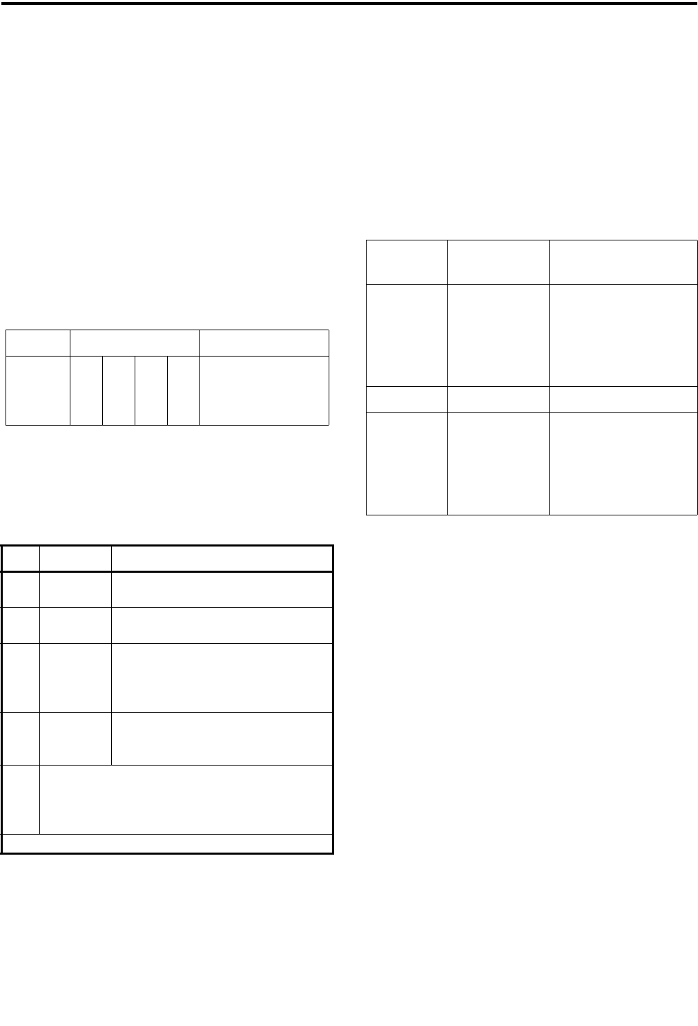
Table 12-2 IDM BOARD JUMPER
PLACEMENT
JU Pin Description
J24 1 to 2*
2 to 3
Selects 27512 EPROM operation
Selects 27256 EPROM operation
J27 1 to 2
2 to 3*
Not Used
Normal Operation
P33 1 to 2*
3 to 4*
5
6
No personality card attached
No personality card attached
open
open
J36 1 only*
1 to 2
2 to 3
Not used
-48V E-lead operation
-15V E-lead operation
J14
J15
J21
J22
Jumper pin 1 to 2 for high impedance ground path
for split 600 ohm inputs and outputs. Leave open if
no ground path desired.
*Setting for Normal operation.
Table 12-3 BACKPLANE PINOUTS
Backplane
P34 to P45 Description
Wire Harness
J1,3,5,7
pin 27
pin 28
pin 29
pin 30
pin 31
pin 32
Sec Rx +
Sec Rx -
EA lead
EB lead
Pri Rx Audio+
Pri Rx Audio-
pin 1
pin 2
pin 3
pin 4
pin 5
pin 6
Signal
Ground
J2,4,6,8
pin 59
pin 60
pin 61
pin 62
pin 63
pin 64
Sec Tx +
Sec Tx -
MA lead
MB lead
Pri Tx Audio+
Pri Tx Audio-
Signal
Ground
pin 1
pin 2
pin 3
pin 4
pin 5
pin 6