


SYSTEM RACK
4-24
2. All PTMs should be installed and configured as
follows:
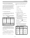
Switch Sections Closed Sections Open
S5, S7 3,4,5,6,7 1,2
S6, S8 2,3,6 1,4,5,7,8
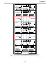
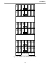
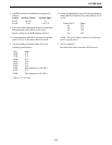
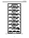
3. Select one of the 8 Backplane boards for measuring.
Measurements can be made on any of the
64-pin connectors on the Backplane selected.
4. All measurements should be referenced to ground
(pins 9, 10, 41 or 42) unless otherwise noted.
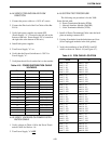
5. All test readings should be within 5% of the
following specifications:
Pins Ohms
16/48 37.5
17/49 37.5
18/50 37.5
19/51 75.0
20/52 37.5
21/53 37.5
22/54 100 (measured to +5V DC*)
23/55 37.5
24/56 100 (measured to +5V DC*)
* Pins 11, 12, 43 or 44.
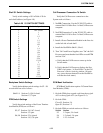
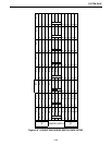
6. On the top Backplane board, the following measure-
ments should be referenced to ground (pins 9, 10, 41
or 42).
Center Pin of Ohms
J5 37.5
J6 37.5
J23 19.2
J24 19.2
NOTE: The four readings should be ±1 ohm from
the test specifications.
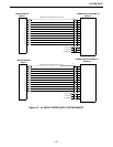
7. Test is completed.
Disconnect the cables from the Call Processor.