


11-1
DISPATCH INTERFACE MODULE (DIM)
SECTION 11 DISPATCH INTERFACE MODULE (DIM)
11.1 DESCRIPTION
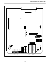
Refer to 3000 Series Switch Service Information
manual, Part No. 001-3139-102, for the component
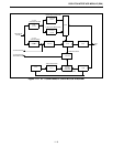
layout, parts list and schematic. Refer to Figure 7-1 for
the Basic Board block diagram. The Dispatch Inter-
face Module (DIM) uses one of two methods of inter-
face to the dispatch equipment:
1. Direct Connection
2. Tone Remote
A DIM with direct connection is associated with
only one group code and uses a form of Type II E&M
lead input similar to the mobile PTT.
A DIM with tone remote connection decodes
guard tone for the PTT indication and decodes DTMF
to select from one of ten group codes. A control
sequence uses the DTMF to place the DIM in scan
mode or to stop and use a specific group code. The
tone remote feature requires the use of a plug-in
personality card.
The DIM connects the 4-Wire 600 ohm balanced
audio with the Pulse Code Modulation (PCM) data
paths and communicates to other modules via the
Intra-Terminal Data Bus (IDB). The DIM also moni-
tors the Channel Interface Module (CIM) Channel
Status Bus (CSB) to determine if a CIM is active with
a DIM group.
11.2 DIM SETUP PROCEDURE
11.2.1 SWITCH SETTINGS
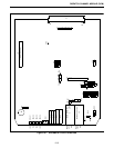
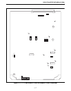
Refer to Figure 11-1 for Alignment Points
Diagram.
Command and Control Communication
The command and control communication to the
Consoles may take the place by two different forms.
The form chosen is typically dependent upon the type
of console connected to the DIM.
1. If the Console is a normal contact closure PTT, the
connection is by direct connect. This uses the E&M
lead input and output.
2. A Tone Remote Console uses 4-Wire audio for the
connection. The DIM requires the use of a tone
remote personality card.
11.2.2 DIM JUMPER PLACEMENT
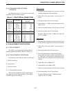
Table 11-1 DIM SWITCH SETTINGS
Switch Open Sections Close Sections
Direct Connection
S1
S3
S4
S5
1
1
1
-
2
2
2
-
-
3
3
-
4
4
4
-
-
-
-
1
-
-
-
2
3
-
-
3
-
-
-
4
Tone Remote
S1
S3
S4
S5
1
1
1
-
2
2
2
-
3
3
3
-
4
4
4
-
-
-
-
1
-
-
-
2
-
-
-
3
-
-
-
4
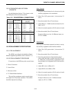
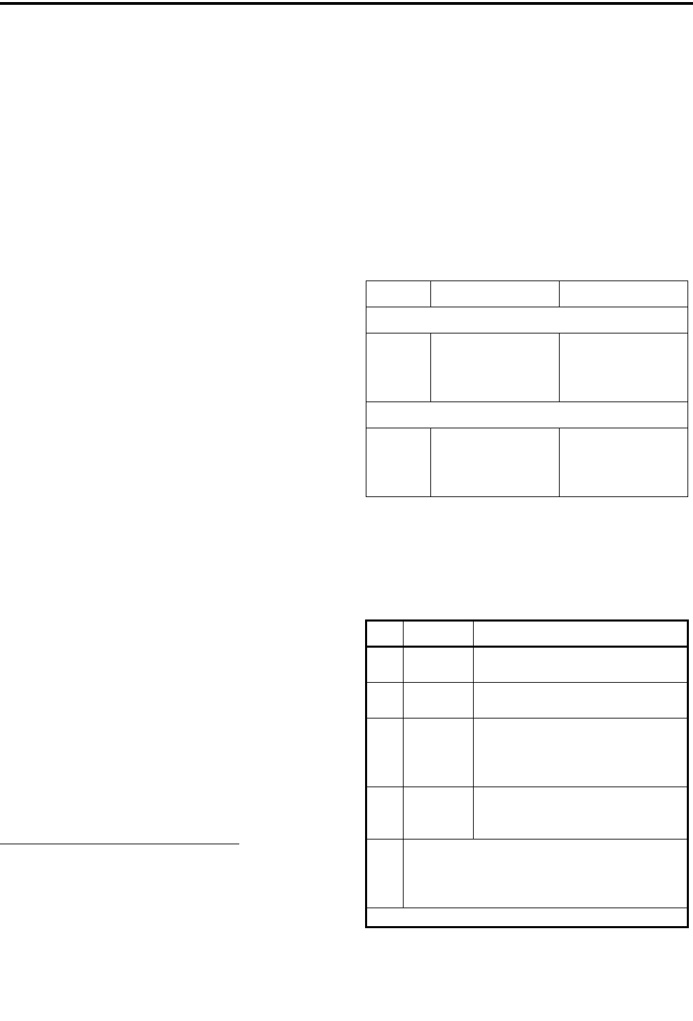
Table 11-2 DIM BOARD JUMPER
PLACEMENT
JU Pin Description
J24 1 to 2*
2 to 3
Selects 27512 EPROM operation
Selects 27256 EPROM operation
J27 1 to 2
2 to 3*
Not Used
Normal Operation
P33 1 to 2*
3 to 4*
5
6
No personality card attached
No personality card attached
open
open
J36 1 only*
1 to 2
2 to 3
Not used
-48V E-lead operation
-15V E-lead operation
J14
J15
J21
J22
Jumper pin 1 to 2 for high impedance ground path
for split 600 ohm inputs and outputs. Leave open if
no ground path desired.
*Setting for Normal operation.