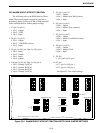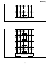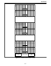
BACKPLANE
23-4
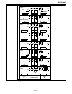
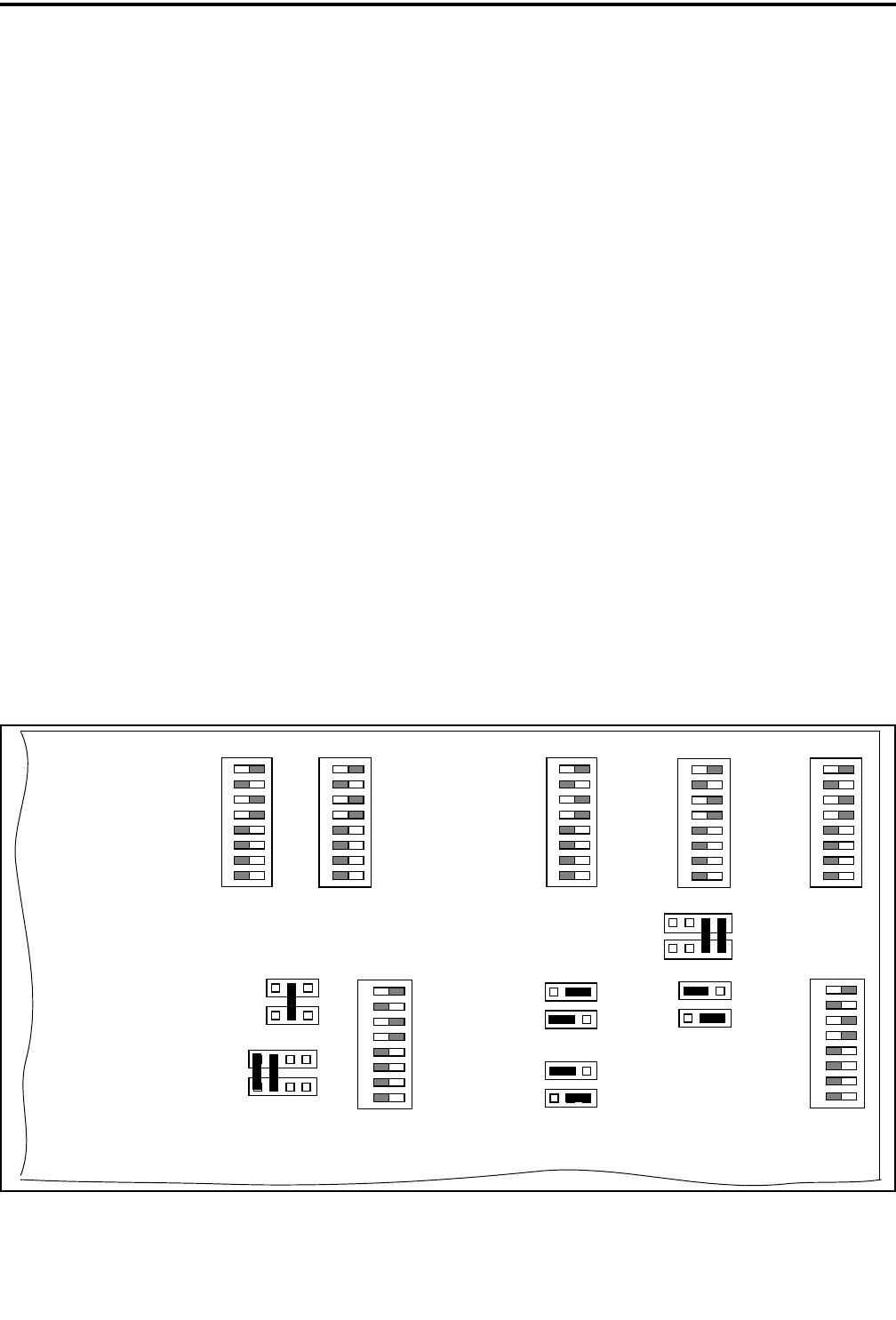
23.5 NetNIM SHELF WITH CIM/CCMs
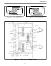
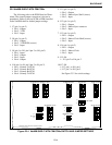
The following refer to the PCM Receiver/Trans-
mitter. The normal jumper connection is shown in
parenthesis. Refer to the card (CIM or DIM) installed
in the NetNIM shelf for further jumper settings.
1. J7 (pin 1 to pin 2)
• Pin 1 - Output
• Pin 2 - VTM
• Pin 3 - Input
2. J8 (pin 1 to pin 2)
• Pin 1 - Output
• Pin 2 - VTM PCM (source)
• Pin 3 - Input
3. J9 (pin 1 to J10, pin 1/pin 2 to J10, pin 2)
• Pin 1 - Input
• Pin 2 - Output
• Pin 3 - Input
• Pin 4 - Output
4. J10 (pin 1 to J9, pin 1/pin 2 to J9, pin 2)
• Pin 1 - Primary Tx PCM
• Pin 2 - Primary Rx PCM
• Pin 3 - Primary Rx PCM
• Pin 4 - Primary Tx PCM
5. J11 (pin 1 to pin 2)
• Pin 1 - Output
• Pin 2 - Master Sync Shelf (source)
• Pin 3 - Input
6. J12 (pin 1 to pin 2)
• Pin 1 - Output
• Pin 2 - Master Sync connector
• Pin 3 - Input
7. J13 (pin 1 to pin 2)
• Pin 1 - Output
• Pin 2 - Master Clock Shelf (source)
• Pin 3 - Input
8. J14 (pin 1 to pin 2)
• Pin 1 - Output
• Pin 2 - Master Clock
• Pin 3 - Input
9. J15-J16
• J15, pin 2 to J16, pin 2
10.J17-J18
• J17, pin 1 to J18, pin 1
• J17, pin 2 to J18, pin 2
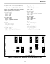
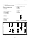
See Figure 23-2 for switch settings.
Figure 23-4 NetNIM SHELF WITH CIM/CCMs SWITCH AND JUMPER SETTINGS
SEC PCM
J18
J17
J16
J15
1
1
1
1
SWITCH SETTINGS ARE FOR A 6-SHELF SYSTEM
J14
J13
J11
J12
1
1
J8
J7
J10
J9
1
1
1
1
1
1
S3 PRI TX PCM
S2 VTM PCM
S4 PRI RX PCM
S5 MASTER SYNC
S7 SEC RX PCM
S6 MASTER CLOCK
S8 SEC TX PCM
1
2
3
4
5
6
7
8
ON
1
2
3
4
5
6
7
8
ON
1
2
3
4
5
6
7
8
ON
1
2
3
4
5
6
7
8
ON
1
2
3
4
5
6
7
8
ON
1
2
3
4
5
6
7
8
ON
1
2
3
4
5
6
7
8
ON
MASTER SYNC
MASTER CLOCK
VTM PCM
Tx/Rx PCM


