


15-1
VOTER DIAGNOSTICS MODULE (VDM)
SECTION 15 VOTER DIAGNOSTICS MODULE (VDM)
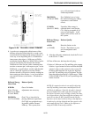
15.1 DESCRIPTION
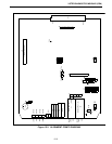
Refer to 3000 Series Switch Service Information
manual, Part No. 001-3139-102, for the component
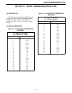
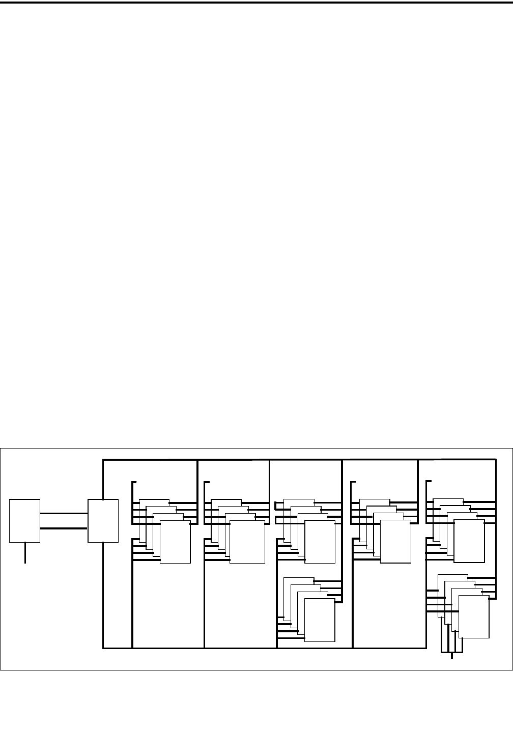
layout, parts list and schematic. Refer to Figure 15-1
for the Basic Board block diagram. The Voter Diag-
nostics Module (VDM) controls the receiver voter
system. This module communicates to the Call
Processor via the Intra-Terminal Data Bus (IDB) and
to the Receiver Voter Module(s) (RVM) via the Voter
Control Bus (VCB). Voice communication does not
take place on this module.
Refer to Voter Manual 001-3139-500 for more
information on the VDM and the Voter system.
The VDM has the ability to enable and disable
channels and sites, to inquire on the received signal
strengths, and receive alarms from the RVMs.
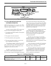
15.2 VDM SETUP PROCEDURE
15.2.1 SWITCH SETTINGS
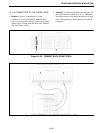
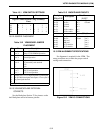
Refer to Figure 15-3 for Alignment Points
Diagram.
Command and Control Communication
The command and control communication to the
RVMs is by 1200 baud RS-232 data communication to
the VCB via the secondary lines.
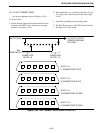
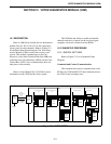
Figure 15-1 DATA BUSES
CIMs CCMs
(NetIDB)
DATA BUS
INTRA-TERMINAL
NETWORK
(NetCSB)
STATUS BUS
CHANNEL
NETWORK
NETWORK
INTERFACE
MODULE
NetNIM
(CIB)
CHANNEL INTERFACE BUS
CONVENTIONAL
CHANNEL
MODULE
INTERFACE
CHANNEL
MODULE
INTRA-TERMINAL DATA BUS (IDB)
(CIB)
CHANNEL INTERFACE BUS
CHANNEL STATUS BUS (CSB)
DISPATCH
MODULE
CHANNEL
DCMs
PSTN OR PABX
TELEPHONE
MODULE
INTERFACE
TIMs
NETWORK
SYSTEM
MODULE
SNMs
SYSTEM NETWORK BUS (SNB)
CALL
PROCESSOR
WIDE
MODULE
AREA
WA Ms
LOGGING
MODULE
ENCODER
LEMs
LOGGING RECORDER
ETHERNET
BUS