


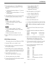
SYSTEM RACK
4-9
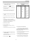
4.2.9 SYSTEM TEST PROCEDURE
The following test procedure is for the Switch
with six Power Termination Modules (PTMs), one
Network Interface Module (NetNIM) and one Voice
Termination Module (VTM).
1. Install all Power Termination Cables onto the back-
plane at mating connector P33.
2. Unplug all modules from the backplane card slots
(leave unplugged modules in the card guides).
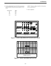
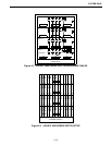
3. Verify the installation of the PCM W1 and W3
cables as shown in Table 4-14 (see Figure 4-5).
Shelf S1 Switch Settings
Verify switch settings of S1 in Table 4-15 for
each shelf address (see Figure 4-5).
Backplane Switch Settings
Verify the backplane switch settings for S2 - S8
on each shelf are set as follows:
Shelf 1-4 section 1 closed
sections 2,3,45,6,7,8 open
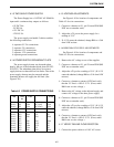
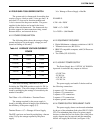
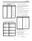
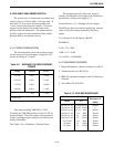
Table 4-8 POWER DISTRIBUTION CABLE
VOLTAGES
Pin Color
1 Green -48V ±2V
2 Not Used None
3 Black Common
4 White -12V ±1V
5 Not Used None
6 Black Common
7 Red +5V +0.5/-0.1V
8 Not Used +12V ±1V
9 Black Common
10 Red +5V +0.5/-0.1V
11 Blue +12V ±1V
12 Black Common
13 Red +5V +0.5/-0.1V
14 Blue +12V ±1V
15 Black Common
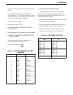
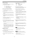
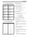
Table 4-9 PCM CABLE LOCATION
From To
Shelf 1 - J25
Shelf 1 - J5
Shelf 1 - J6
Shelf 1 - J23
Shelf 1 - J24
Shelf 1 - J26
Shelf 2 - J3
Shelf 2 - J4
Shelf 2 - J25
Shelf 2 - J26
Shelf 2 - J5
Shelf 2 - J6
Shelf 2 - J23
Shelf 2 - J24
Shelf 3 - J3
Shelf 3 - J4
Shelf 3 - J25
Shelf 3 - J26
Shelf 3 - J5
Shelf 3 - J6
Shelf 3 - J23
Shelf 3 - J24
Shelf 4 - J3
Shelf 4 - J4
Shelf 4 - J25
Shelf 4 - J26
Shelf 4 - J5
Shelf 4 - J6
Shelf 4 - J23
Shelf 4 - J24
Shelf 5 - J3
Shelf 5 - J4
Shelf 5 - J25
Shelf 5 - J26
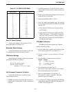
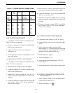
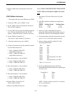
Table 4-10 S1 SWITCH SETTINGS
Shelf Number Switch 1, Open Sections
1
2
3
4
5
6
7
8
9
10
11
12
13
14
15
16
17
18
ALL Closed
1
2
1,2
3
1,3
2,3
1,2,3
4
1,4
2,4
1,2,4
3,4
1,3,4
2,3,4
1,2,3,4
5
1,5