13-1
SYSTEM NETWORK MODULE (SNM)
SECTION 13 SYSTEM NETWORK MODULE (SNM)
13.1 DESCRIPTION
Refer to 3000 Series Switch Service Information
manual, Part No. 001-3139-102, for the component
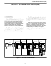
layout, parts list and schematic. Refer to Figure 7-1
for the Basic Board block diagram. The System
Network Module (SNM) is the interface that allows
Unique ID calling from RF units and multiple
Switches to be connected in a total system network.
The SNM uses a 4-wire 600 ohm balanced audio
on the interface and connects audio to the PCM data
paths. The SNM also uses a Type II E&M lead
connection set for connection initiation and supervi-
sion.
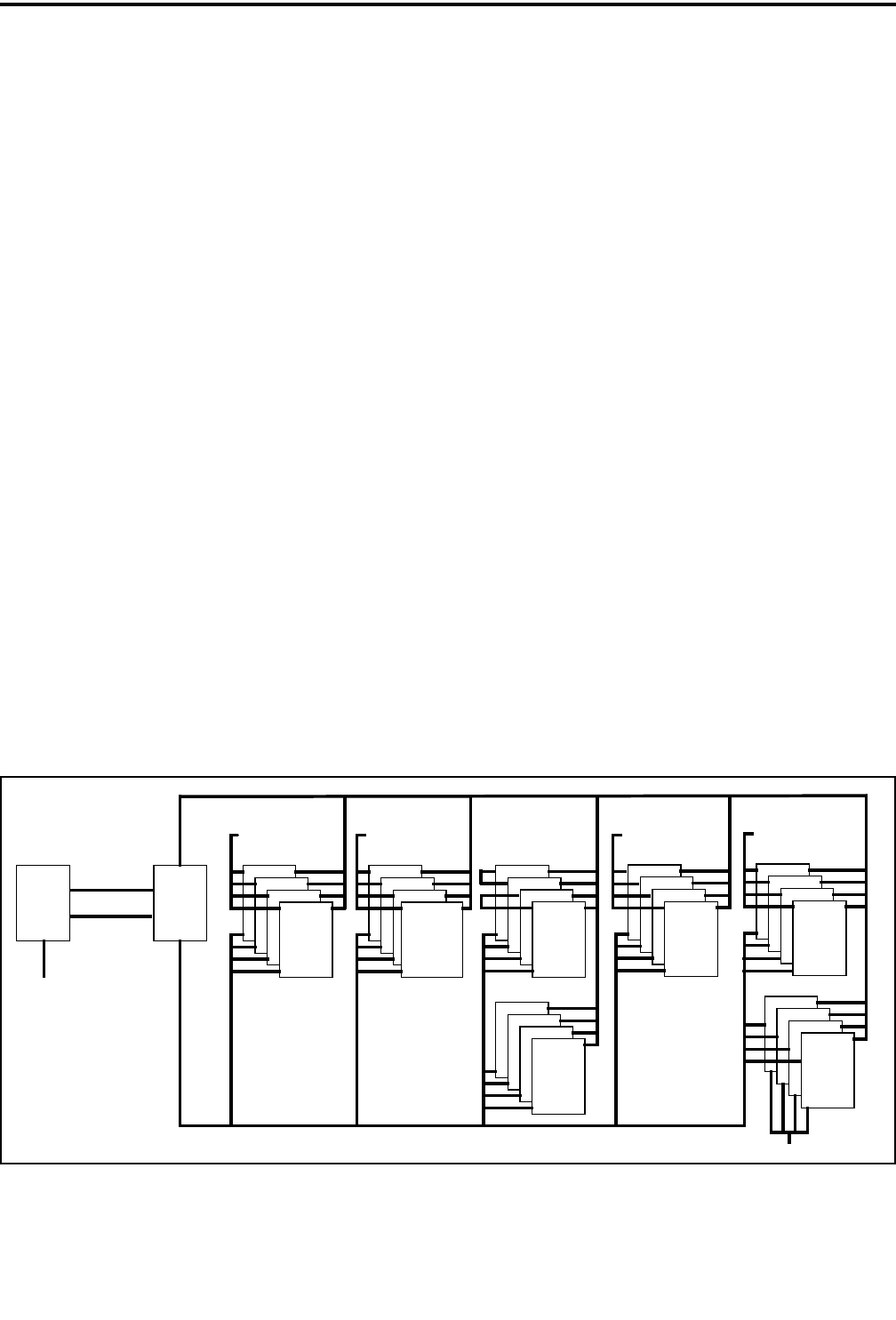
The SNM communicates with other modules via
the Intra-Terminal Data Bus (IDB) and monitors the
Channel Status Bus (CSB) for the group set up to use
the SNM.
SNMs pass information on the interface relative
to the type of call desired and connection status of the
end device, using Audio Frequency Shift Keying
(AFSK) data in a blank and burst mode. This form of
data passing allows a standard 4-Wire interface
connection and does not require a specialized system
switching node.
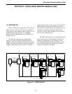
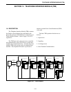
Figure 13-1 DATA BUS BLOCK DIAGRAM
CIMs CCMs
(NetIDB)
DATA BUS
INTRA-TERMINAL
NETWORK
(NetCSB)
STATUS BUS
CHANNEL
NETWORK
NETWORK
INTERFACE
MODULE
NetNIM
(CIB)
CHANNEL INTERFACE BUS
CONVENTIONAL
CHANNEL
MODULE
INTERFACE
CHANNEL
MODULE
INTRA-TERMINAL DATA BUS (IDB)
(CIB)
CHANNEL INTERFACE BUS
CHANNEL STATUS BUS (CSB)
DISPATCH
MODULE
CHANNEL
DCMs
PSTN OR PABX
TELEPHONE
MODULE
INTERFACE
TIMs
NETWORK
SYSTEM
MODULE
SNMs
SYSTEM NETWORK BUS (SNB)
CALL
PROCESSOR
WIDE
MODULE
AREA
WA Ms
LOGGING
MODULE
ENCODER
LEMs
LOGGING RECORDER
ETHERNET
BUS


