


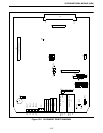
TELEPHONE INTERFACE MODULE (TIM)
14-7
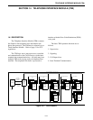
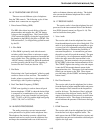
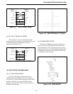
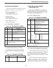
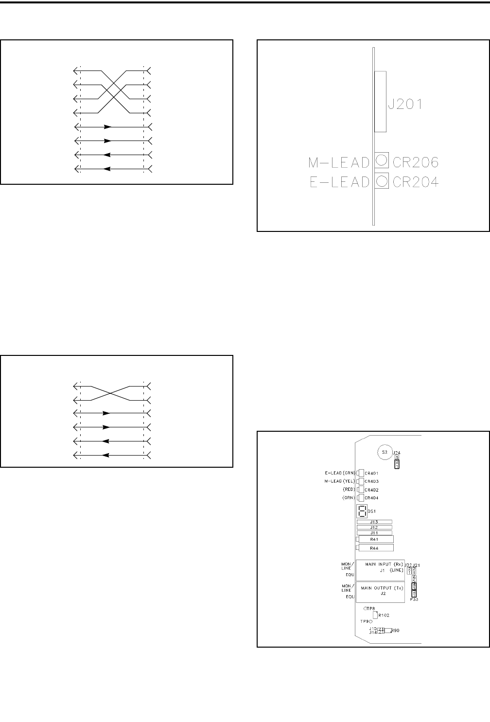
Figure 14-7 TYPE II TRUNK-TRUNK
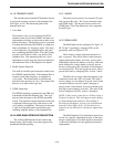
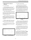
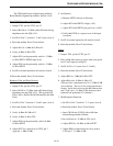
14.2.8 TYPE V TRUNK-TO-TRUNK
This interface is a cross-connect between the
trunk circuits. Four conductors are balanced audio and
the M-Lead and E-Lead conductors are cross-
connected (see Figure 14-8).
Figure 14-8 TYPE IV TRUNK-TRUNK
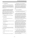
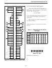
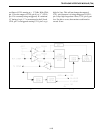
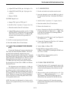
14.3 LED STATUS FOR E&M LEADS
14.3.1 TELCO SIDE STATUS
The Telco Side Status can be monitored on
CR206 (M-Lead) and CR204 (E-Lead) see Figures
14-9 and 14-21. These LEDs are used to show a status
change on the Telco side of the E&M Personality
Board. In some instances either or both could be illu-
minated in the idle state.
Figure 14-9 E&M PERSONALITY BOARD
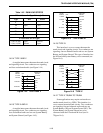
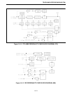
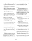
14.3.2 E&M LOGIC STATUS
The status of E&M Logic can be monitored on
CR401 (E-Lead) and CR403 (M-Lead) of the main
board (see Figure 14-10). These are logic levels that
display the true status of the E&M leads. If either LED
is illuminated, that lead is active. Both LEDs should
not illuminate in the idle state.
Figure 14-10 MAIN BOARD
TRUNK
CIRCUIT
E-LEAD
M-LEAD
RX AUDIO
TX AUDIO
TR1
RR1
T1
R1
E-LEAD
M-LEAD
RNT
SIGNALING
CIRCUIT
SB
SG
SB
SG
TRUNK
CIRCUIT
E-LEAD
M-LEAD
RX AUDIO
TX AUDIO
TR1
RR1
T1
R1
E-LEAD
M-LEAD
RNT
SIGNALING
CIRCUIT