


CHANNEL INTERFACE MODULE (CIM)
8-2
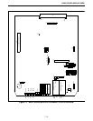
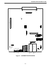
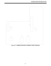
8.2.2 JUMPER PLACEMENT
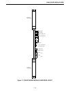
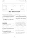
8.2.3 CIM BACKPLANE EXTERNAL CONTACTS
See the Backplane Section 23 for pin-outs on the
shelf backplane and wire harness pinouts.
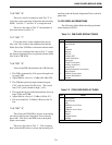
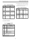
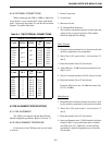
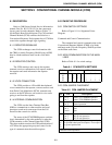
Table 8-1 CIM SWITCH SETTINGS
Switch Open Sections Close Sections
Digital Communication Using Secondary Lines
S1
S3
S4
S5
1
1
-
-
2
2
-
-
-
-
3
-
4
-
4
-
-
-
1
1
-
-
2
2
3
3
-
3
-
4
-
4
AFSK Communication Using Secondary Lines
S1
S3
S4
S5
-
-
1
-
2
-
2
-
-
3
-
-
4
4
-
-
1
1
-
1
-
2
-
2
3
-
3
3
-
-
4
4
AFSK Communication On The Main Line
S1
S3
S4
S5
1
1
1
-
-
2
2
-
-
3
3
-
4
4
4
-
-
-
-
1
2
-
-
2
3
-
-
3
-
-
-
4
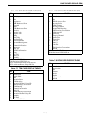
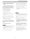
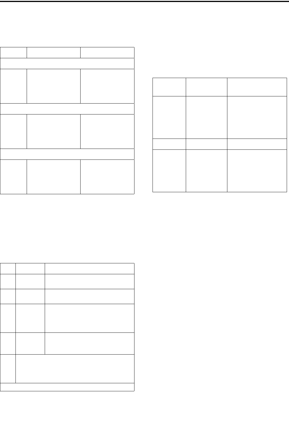
Table 8-2 CIM BOARD JUMPER
PLACEMENT
JU Pin Description
J24 1 to 2*
2 to 3
Selects 27512 EPROM operation
Selects 27256 EPROM operation
J27 1 to 2
2 to 3*
Not Used
Normal Operation
P33 1 to 2*
3 to 4*
5
6
No personality card attached
No personality card attached
open
open
J36 1 only*
1 to 2
2 to 3
Not used
-48V E-lead operation
-15V E-lead operation
J14
J15
J21
J22
Jumper pin 1 to 2 for high impedance ground path
for split 600 ohm inputs and outputs. Leave open
if no ground path desired.
*Setting for Normal operation.
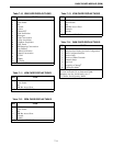
Table 8-3 BACKPLANE PINOUTS
Backplane
P34 to P45
Description
Wire Harness
J1,3,5,7
pin 27
pin 28
pin 29
pin 30
pin 31
pin 32
Sec Rx +
Sec Rx -
EA lead
EB lead
Pri Rx Audio+
Pri Rx Audio-
pin 1
pin 2
pin 3
pin 4
pin 5
pin 6
RxS+
RxS-
EA
EB
RxA+
RxA-
J2,4,6,8
pin 59
pin 60
pin 61
pin 62
pin 63
pin 64
Sec Tx +
Sec Tx -
MA lead
MB lead
Pri Tx Audio+
Pri Tx Audio-
TxS+
TxS-
MA
MB
TxA+
TxA-
pin 1
pin 2
pin 3
pin 4
pin 5
pin 6