


21-1
CONVENTIONAL PATCH MODULE (CPM)
SECTION 21 CONVENTIONAL PATCH MODULE (CPM)
21.1 DESCRIPTION
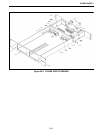
Refer to 3000 Series Switch Service Information
manual, Part No. 001-3139-102, for the component
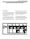
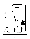
layout, parts list and schematic. Refer to Figure 8-1
for the Basic Board Block diagram.
The Conventional Patch Module (CPM) is used
to dynamically patch a single conventional channel to
a single trunked group. The Switch can hold two
CPMs per MCM. The CPMs must be adjacent to the
controlling MCM (e.g. the MCM is at Slot 8005 so the
CPMs must be placed in Slots 8006 and 8007). No
other cards may be placed in these slots. If the user
wishes to patch a conventional channel to more than
one trunk group the following procedure must be
used.
1. A trunk group is chosen for the CPM patch, (e.g.
Site 1, Home 1, Group 1 (S1H1G1) and the conven-
tional channel is chosen or vice versa.
2. The trunk group chosen for the CPM patch
(S1H1G1) must be placed in a group patch with the
other trunk groups for the patch in a Wide Area
Module (WAM) patch.
A CPM with direct connection is associated with
only one group code and uses a form of Type II E&M
lead input similar to the mobile PTT.
The CPM connect the 4-Wire 600 ohm balanced
audio with the Pulse Code Modulation (PCM) data
paths and communicates to other modules via the
Intra-Terminal Data Bus (IDB). The CPM also moni-
tors the Channel Interface Module (CIM) Channel
Status Bus (CSB) to determine if a CIM is active with
a CPM group.
21.2 PCM SETUP PROCEDURE
21.2.1 SWITCH SETTINGS
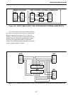
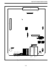
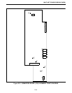
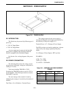
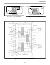
Refer to Figure 21-1 for Alignment Points
diagram.
Command and Control Communication
The command and control communication to the
Consoles may takes place by direct contact with E&M
input and output.
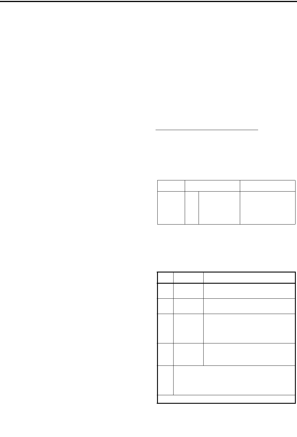
21.2.2 CPM JUMPER PLACEMENT
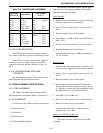
Table 21-1 CPM SWITCH SETTINGS
Switch Open Sections Close Sections
S1
S3
S4
S5
1
1
1
-
2
2
2
-
-
3
3
-
4
4
4
-
-
-
-
1
-
-
-
2
3
-
-
3
-
-
-
4
Table 21-2 CPM BOARD JUMPER
PLACEMENT
JU Pin Description
J24 1 to 2*
2 to 3
Selects 27512 EPROM operation
Selects 27256 EPROM operation
J27 1 to 2
2 to 3*
Not Used
Normal Operation
P33 1 to 2*
3 to 4*
5
6
No personality card attached
No personality card attached
open
open
J36 1 only*
1 to 2
2 to 3
Not used
-48V E-lead operation
-15V E-lead operation
J14
J15
J21
J22
Jumper pin 1 to 2 for high impedance ground path
for split 600 ohm inputs and outputs. Leave open if
no ground path desired.
*Setting for Normal operation.