


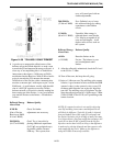
TELEPHONE INTERFACE MODULE (TIM)
14-25
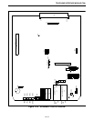
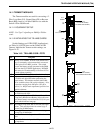
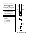
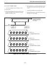
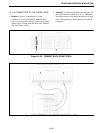
14.11.4 XEL TERMSET RACK
Set up the equipment shown in Figures 14-24,
14-25 and 14-26.
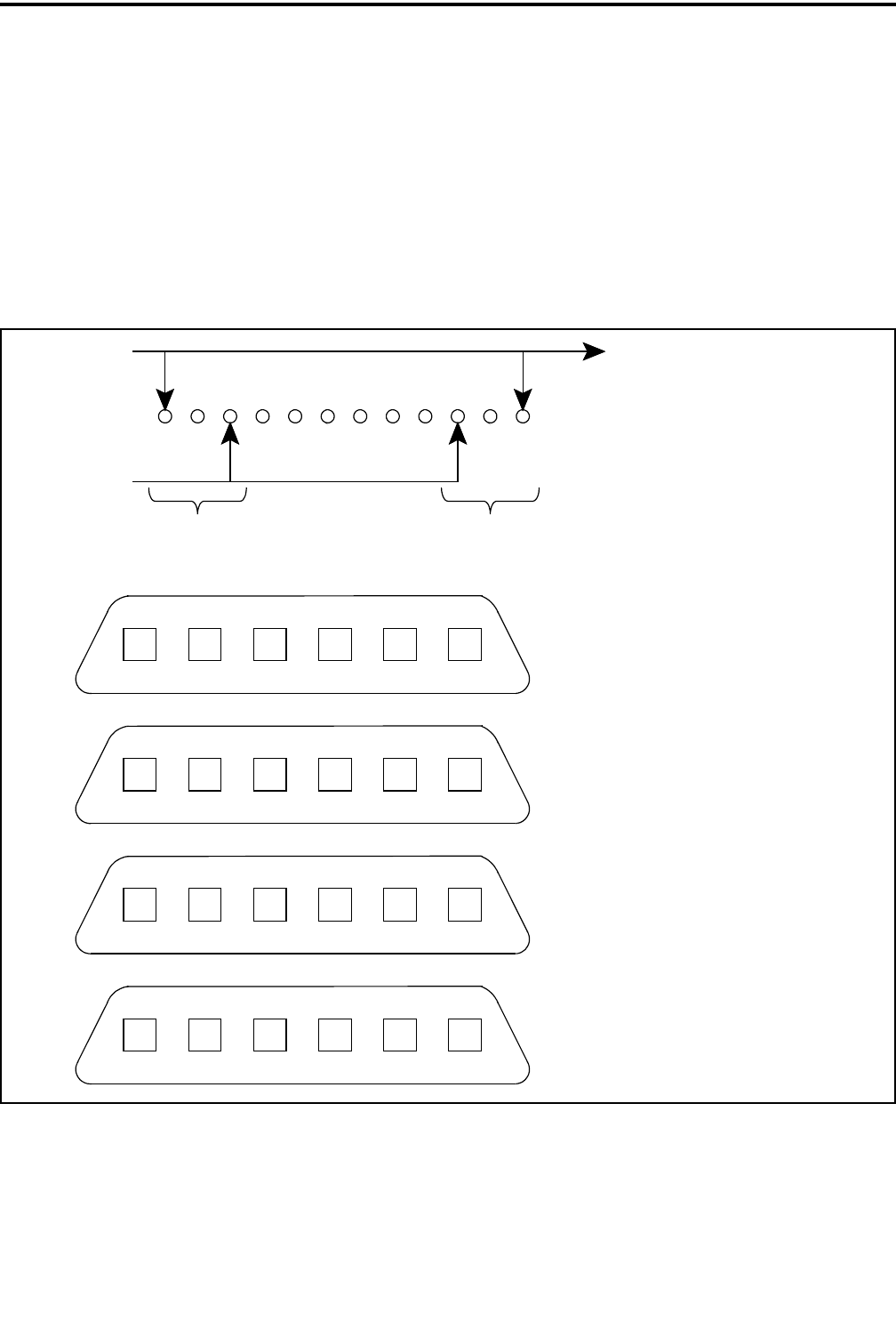
1. Ensure that the jumpers have been installed on the
backside of the XEL rack, where the power plug
attaches (see Figure 14-24).
2. Ensure that there is a connection from Slot-12, pin
27 to the power connector ground pin (see Figure
14-24).
3. Attach the grounding strap to earth ground.
4. The XEL Rack requires -48V DC from the Switch.
See Figure 14-24 for wiring.
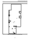
Figure 14-24 XEL TERMSET RACK (REAR CLOSE-UP)
POWER FOR
SLOTS 1-6
POWER FOR
SLOTS 7-12
TO SLOT-12, PIN 27
CHASSIS GROUND
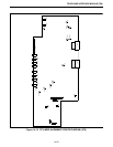
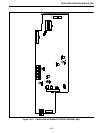
XEL RACK
J1 CONNECTION TO CO
J2 CONNECTION TO CO
J3 CONNECTION TO E&M
J4 CONNECTION TO E&M
SLOTS 7-12
SLOTS 1-6
SLOTS 7-12
SLOTS 1-6654321
12 11 10 9 8 7
654321
12 11 10 9 8 7
-48V
FROM SWITCH
SWITCH-GND