TELEPHONE INTERFACE MODULE (TIM)
14-17
14.10 E&M SETUP AND ALIGNMENT (-680)
The standard audio signal is defined as a 1 kHz
audio tone modulated at 2 kHz deviation, with data
modulated at 1 kHz deviation (total deviation is
3 kHz).
14.10.1 EQUIPMENT REQUIRED
1. Digital storage scope (Tektronix 2430 or equivalent
with roll mode trigger capability from 100 ms to 1
second).
2. Printer or plotter for scope (recommended for
sending data back to E.F. Johnson for analysis).
3. Telephone test set (Ameritec V.F. test set model
AM-44 or equivalent).
4. RF communications monitor.
5. Multi-Net Encoder/Decoder Box.
14.10.2 TRANSMIT ALIGNMENT
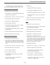
DTMF Transmit Level Adjust
1. Set S5 on the main board for Test 3
(sections 1 and 2 open, 3 and 4 closed).
2. Adjust R214 for -7 dB at TP201 (EP201). This sets
the correct level of TX DTMF with respect to TX
Audio.
NOTE: After adjusting this level, DTMF and audio
are adjusted together by R44 (TX+/TX-). TX+ DTMF
and audio are monitored at J12.
Transmit Audio Level Adjust
This procedure requires a fully tuned repeater for
testing. Test this repeater by keying up in dispatch
mode with a radio. Monitor the receive frequency and
record the receive data level. Generate a DTMF 5
from the radio and record the total deviation of data +
audio. Subtract the previous data level and record the
audio level received.
Monitor the transmit frequency of the repeater.
Key up the radio and record the transmit data level.
Generate a DTMF 5 from the radio and record the
total deviation of data + audio. Subtract the data level
previously recorded and record the audio level
received. This level of audio should be the same as
the receive level. If not, retune the repeater before
proceeding with this procedure.
Disable dial-tone detection in the Call Processor.
With a known good repeater, attempt to make a call to
a test phone over the 4-Wire circuit. If the call did not
go through, check digit timing parameters (pulse and
DTMF) or the level of DTMF transmitted at TX+/TX-
. Normally this level is -7 dBm (346 mV RMS or
978 mV P-P). If the 4-Wire requires a different level
adjust R44 while monitoring the transmit level for the
appropriate level.
Once the call is connected to a test phone (a
phone located at the site provided the call went
through the CO or PBX), collect the repeater using the
Multi-Net Encoder/Decoder box and communications
monitor with a data level of 1 kHz. With the call still
going, turn off the radio (do not pound '#' down the
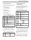
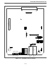
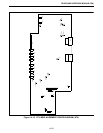
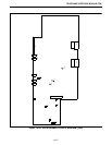
Table 14-7 E&M MAIN BOARD JUMPERS
JU Pin Description
J24 1 to 2*
2 to 3
Selects 27512 EPROM operation
Selects 27256 EPROM operation
J27 1 to 2
2 to 3*
Not used
Normal operation
P33 1 to 2
3 to 4
5 and 6
open
open
open
J36 2 to 3 For E&M operation
J14
J15
J21
J22
Jumper pin 1 to 2 for high impedance ground path
for split 600 ohm inputs and outputs. Leave open if
no ground path desired.
* Indicates normal operation.
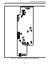
Table 14-8 E&M JUMPER PLACEMENT
JU Pin Description
J207 1 to 2
2 to 3
Connects Dial Tone circuit
Removes Dial Tone circuit
J209 1 to 2 Connects SG to Switch 0V (gnd)


