


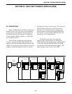


CONVENTIONAL PATCH MODULE (CPM)
21-2
21.2.3 E-LEAD SELECTION
If the PTT from the console is an open contact
relay, either of the above options for J36 may be used.
If the PTT is a closure to ground with a pull-up
resistor to a positive voltage, J36, pin 2 should be
connected to ground without connection to pin 1 or
pin 3.
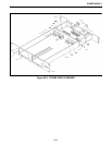
21.2.4 CPM BACKPLANE EXTERNAL
CONTACTS
See the Backplane Section 23 for pinouts on the
shelf backplane and wire harness pinouts.
21.3 CPM ALIGNMENT SPECIFICATION
21.3.1 PRE-ALIGNMENT
The CPM is pre-aligned with the Basic Board
Module alignment procedures (Refer to Section 8.3).
21.3.2 ALIGNMENT
Connections to the CPM may take several forms:
1. Direct Connection
2. Leased Lines
3. Microwave Link
4. T1 Channel Bank Interfaces
This ancillary equipment requires certain input
and output levels for proper operation. The module
should be adjusted accordingly.
Main Transmit
1. Determine the maximum level to be received by the
ancillary equipment to be transmitted.
2. Set S5 to Test 1 (open section 1, close sections 2, 3
and 4).
3. Reset the module, Press S2 and release.
4. Adjust R44 for -12 dB from the maximum level in
Step 1 at J12.
5. Set S5 for normal operation (all sections closed).
6. Reset the module, Press S2 and release.
Example: Microwave has -16 dBm max input, set
J12 for -28 dBm.
Main Receive
1. Determine the maximum transmit level that is sent
by the ancillary equipment to the interface module.
2. Set S5 to Test 1 (open section 1, close sections 2, 3
and 4).
3. Reset the module, Press S2 and release.
4. Insert the maximum level determined in Step 1
using a 600 ohm audio oscillator into EQU port of
J1. Otherwise, set the ancillary equipment to send
the alignment tone to the interface module.
5. Adjust R41 to be -6 dBm at J11.
6. Set S5 for normal operation (all sections closed).
7. Reset the module, Press S2 and release.
Example: Microwave has +7 dBm maximum
output, set J11 for -5 dBm.
Secondary Transmit and Receive
Not aligned since the CPM does not use FSK
signaling.
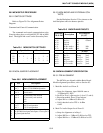
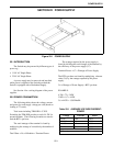
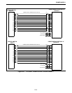
Table 21-3 BACKPLANE PLACEMENT
Backplane
P34 to P45
Description
Wire Harness
J1,3,5,7
pin 27
pin 28
pin 29
pin 30
pin 31
pin 32
Sec Rx +
Sec Rx -
EA lead
EB lead
Pri Rx Audio+
Pri Rx Audio-
pin 1
pin 2
pin 3
pin 4
pin 5
pin 6
Signal
Ground
RX+
RX-
J2,4,6,8
pin 59
pin 60
pin 61
pin 62
pin 63
pin 64
Sec Tx +
Sec Tx -
MA lead
MB lead
Pri Tx Audio+
Pri Tx Audio-
Signal
Ground
Tx+
Tx-
pin 1
pin 2
pin 3
pin 4
pin 5
pin 6