


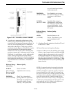

TELEPHONE INTERFACE MODULE (TIM)
14-26
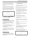
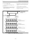
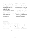
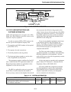
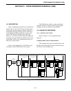
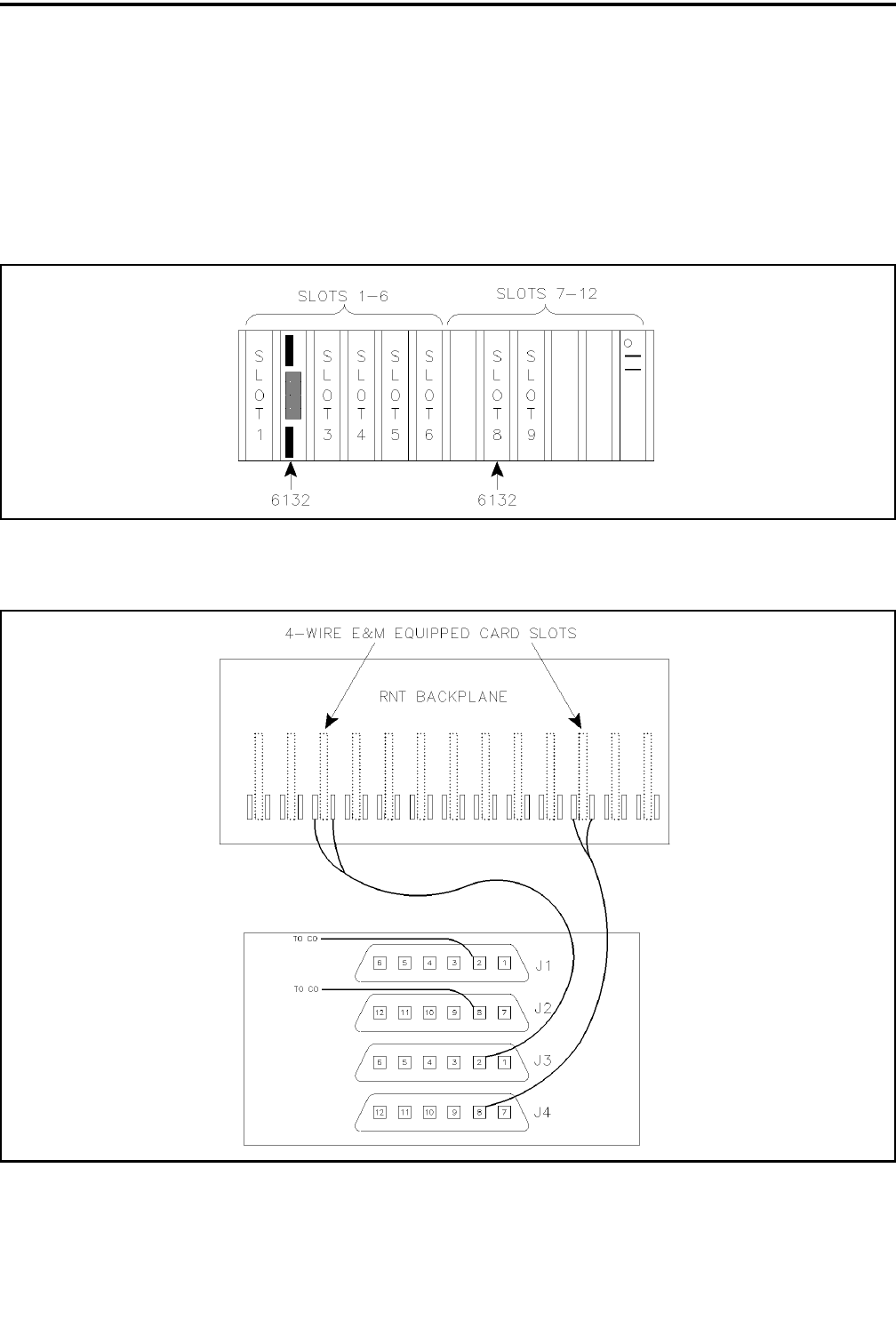
14.11.5 CONNECTION TO THE PHONE LINES
1. Method 1: An RJ-11 harmonica to 50-pin
connector J1 or J2. On the RJ-11 harmonica the
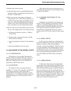
slots 1-6 correspond to the RJ-11 jacks going from
right to left as viewed from the back of the Termset
rack (see Figure 14-26).
2. Method 2: A punch down block and a 50-pin to 50-
pin cable that also attaches to J1 or J2. The phone
lines then connect to the punch down block in posi-
tions corresponding to their location on the 50-pin
connector.
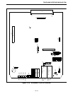
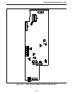
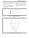
Figure 14-25 TERMSET RACK (FRONT VIEW)
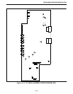
Figure 14-26 NETWORK LINK (SWITCH RACK BACK VIEW)