


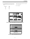
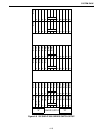
SYSTEM RACK
4-14
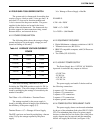
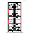
4.3.3 VERIFY RESISTANCE OF BUS BAR AND
POWER SUPPLY LINES
1. Verify the Power Cables are not
connected to a
power source.
2. Verify the Power Supplies are not installed in the
Power Supply shelf.
3. Measure the resistance from point-to-point and
verify the resistance as shown in Table 4-12.
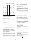
4.3.4 VERIFY COOLING FAN AIR FLOW DIREC-
TION
1. Connect the power cables to a 110V AC source.
2. Connect the Plus lead of the Fan Cable to Bus Bar
D1-16.
3. Verify both power supplies are turned OFF.
(Power Supply "A", is located on the left side at the
bottom of the rack. Power Supply "B" is located on
the right side at the bottom of the rack.)
4. Install both power supplies.
5. Turn Power Supply "A" on.
6. Verify that the Power On indicator is "ON" for
Power Supply "A".
7. Verify that the air flow from the fan is to the outside.
4.3.5 VERIFY VOLTAGES ON POWER DISTRI-
BUTION CABLE
1. Verify voltages in Table 4-13 for the Power Termi-
nation Cables for Shelves 1-6.
2. Turn Power Supply "A" OFF
.
4.3.6 SYSTEM TEST PROCEDURE
The following test procedure is for the Switch
with six Power Termination Modules (PTMs), one
Network Interface Module (NetNIM) and one Voice
Termination Module (VTM).
1. Install all Power Termination Cables onto the back-
plane at mating connector P33.
2. Unplug all modules from the backplane card slots
(leave unplugged modules in the card guides).
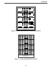
3. Verify the installation of the PCM W1 and W3
cables as shown in Table 4-14 (see Figure 4-5).
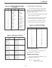
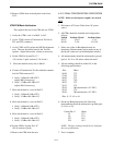
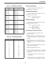
Table 4-13 POWER DISTRIBUTION CABLE
VOLTAGES
Pin Color
1 Green -48V ±2V
2 Not Used None
3 Black Common
4 White -12V ±1V
5 Not Used None
6 Black Common
7 Red +5V +0.5/-0.1V
8 Not Used +12V ±1V
9 Black Common
10 Red +5V +0.5/-0.1V
11 Blue +12V ±1V
12 Black Common
13 Red +5V +0.5/-0.1V
14 Blue +12V ±1V
15 Black Common